Indak Ignition Switch Diagram Wiring Schematic – Let’s first take a look at the different types of terminals used on the ignition switch. These are terminals for the Ignition, Coil, or Accessory. Once we understand the function of each type of terminal, we are able to determine the components of the ignition wiring. Then, we will discuss the functions and the Coil. Then, we will focus on the accessories terminals.
Terminals for ignition switches
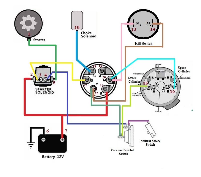
Three switches are found on the ignition switch. Each of these three switches feeds the battery’s voltage to a variety of places. The first switch is the one that supplies the choke with power, while the second switch controls the on/off status of the ignition switch. Different manufacturers utilize their own color-coding method for different conductors that is described in a separate article. OMC utilizes this method. An additional connector is included in the ignition switch for connecting a Tachometer.
While many ignition switch terminals might not be original, the numbers of the terminals may not match the diagram. The first step is to check the continuity of all wires to make sure they’re properly connected to the ignition switches. You can check this using a simple multimeter. After you’re happy with the continuity of the wires connect the new connector. If you have an ignition switch that is supplied by the manufacturer the wiring loom may be different from that you have in your car.
Before connecting the ACC outputs to your car’s auxiliary outputs, it is important to be familiar with the fundamentals of these connections. The ACC/IGN terminals act as the default connection on the ignition switch. The START/IGN terminals connect to the stereo or radio. The ignition switch operates the engine’s off/on button. On older vehicles, the ignition switch terminals are identified with the alphabets “ACC” and “ST” (for distinct magnet wires).
Terminals for coil
To identify the kind of ignition coil, the initial step is to learn the terms. A simple diagram of the wiring will display a range of connections and terminals, comprising two primary and two secondaries. Each coil operates at a specific voltage. The first step to determine which kind you’re dealing with is to test the voltage on S1, or the primary terminal. S1 should be tested for resistance in order to determine if the coil belongs to type A, B and/or C.
The negative of the chassis must be connected to the low-tension side. This is the ground on the ignition wiring diagram. The high tension part supplies positive power directly to the spark plugs. For suppression purposes, the coil’s body metal must be connected with the chassis. This is not necessary to use electricity. The wiring diagram of the ignition will explain how to connect the terminals of either the positive or negative coils. In certain instances it is possible to find an ignition coil that is malfunctioning is easily identified with a scan in an auto parts store.
The black-and-white-striped wire from the harness goes to the negative terminal. The positive terminal also receives a white wire that is black in its trace. The black wire connects with the contact breaker. To check the connections, use a paperclip or a pencil to remove them from the plug housing. Make sure you verify that the connections aren’t bent.
Accessory terminals
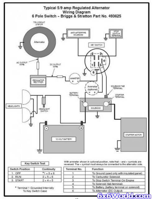
Diagrams of the ignition wiring show the wiring used to supply power to different parts of the car. There are generally four colored terminals that correspond to the respective component. Red refers to accessories, yellow to the battery and green is the starter solenoid. The “IGN” terminal can be utilized to turn on the car, control the wipers, as well as other features. This diagram shows how you can connect ACC and ST terminals to the rest of components.
The battery is connected to the terminal named BAT. The electrical system can’t be started without the battery. Additionally, the switch will not turn on without the battery. It is possible to view your wiring diagram to figure out where the batteries of your car are located. The ignition switch is connected to the car’s battery. The BAT Terminal is connected to the battery.
Certain ignition switches have an additional position. It allows users to connect their outputs to another location without the ignition. Customers sometimes want an auxiliary output that can be used separately from the ignition. Make use of the secondary output by connecting the connector to an ACC terminal on the switch that has the same color. Although this is a fantastic option, there’s a thing you need to know. Most ignition switches will be in an ACC position if the car is in the ACC however, they’ll be at the START position if the vehicle is in IGN.
Gallery of Indak Ignition Switch Diagram Wiring Schematic
Gallery of Indak Ignition Switch Diagram Wiring Schematic


