Ultima Electronic Ignition Wiring Diagram – We’ll begin by looking at different kinds of terminals that are found on an ignition switch. These are terminals for the Ignition, Coil, or Accessory. Once we know the terminals used, we can begin to recognize the various parts of the Ultima Electronic Ignition Wiring Diagram. In addition, we will discuss the roles of the Ignition switch and Coil. The next step is to focus to the accessory terminals.
Terminals for ignition switches
The ignition switch has three switches. They feed the voltage of the battery to many different places. The choke is powered by the first switch. The second switch is responsible for the ON/OFF switch of the ignition switch. Every manufacturer has its unique color-coding system, which we will discuss in another article. OMC employs this system. The ignition switch also includes an adapter for the addition of a tachometer.
Although the majority of ignition switch terminals don’t have an initial number, they could have a different one. The first step is to check the continuity of each wire to ensure that they are properly connected to the ignition switches. This can be done with a simple multimeter. Once you’ve verified that the wires are in good condition, you are able to install the connector. If your vehicle is equipped with an ignition switch that is installed the wiring diagram may differ.
Before you can connect the ACC outputs to the auxiliary outputs of your car, it is important to understand the basics of these connections. The ACC/IGN connections function as the default connections on the ignition switch. The START/IGN terminals connect to the radio or stereo. The ignition switch’s function is to turn the engine of your car on and off. Older cars have the ignition switch terminals marked “ACC” or “ST” (for individual magnetowires).
Terminals for coil
The first step to determine the kind of ignition coil is to comprehend the terms that is used. You will see several connections and terminals on the basic wiring diagram for ignition which includes two primary as well as two secondary. The coils are equipped with a particular operating voltage. The first method of determining what type you’re using is to test the voltage on S1, the main terminal. S1 must also go through resistance testing to determine whether it is a Type A or B coil.
The chassis’ negative end should be connected to connect the coil’s low-tension side. This is what’s called the ground on the ignition wiring diagram. The high-tension supply delivers the spark plugs with positive electricity directly. To reduce the noise the coil’s body metal is required to be connected to the chassis. This is not necessary to use electricity. A wiring diagram can also illustrate the connection between the positive and negative coils. There could be an issue with your ignition coil that can be easily diagnosed by looking it up at an auto parts store.
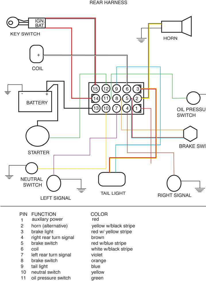
The black-and-white-striped wire from the harness goes to the negative terminal. The other white wire is black and goes to the negative terminal. The black wire connects with the contact breaker. You can take the black wire from the housing of the plug with a paper clip in case you are uncertain about the connection. It’s also crucial to make sure the terminals don’t bend.
Accessory terminals
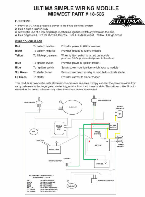
Diagrams of the ignition wiring illustrate the wiring used to provide power to various components of the car. In general there are four colored terminals for each part. The red color represents accessories, yellow for the battery and green for the solenoid for starters. The “IGN terminal” is used to power the wipers as well as other operating features. This diagram shows how you can connect ACC and ST terminals to the rest of the components.
The terminal referred to as BAT is the place where the battery is. The electrical system will not start without the battery. The switch also won’t be able to turn on without the battery. You may refer to the wiring diagram if you’re unsure where your car’s batteries are located. The ignition switch and battery are connected via accessory terminals. The BAT terminal is connected with the battery.
Certain ignition switches come with an accessory position where users can modify their outputs as well as control them without the need to use the ignition. Sometimes, customers want to use an auxiliary output that is not connected to the ignition. You can utilize the auxiliary input by connecting the connector to the ACC terminal. This feature is convenient however it does have one major difference. A majority of ignition switches feature the ACC position when the car is in the ACC mode and a START mode when the switch is in IGN.
Gallery of Ultima Electronic Ignition Wiring Diagram
Gallery of Ultima Electronic Ignition Wiring Diagram


