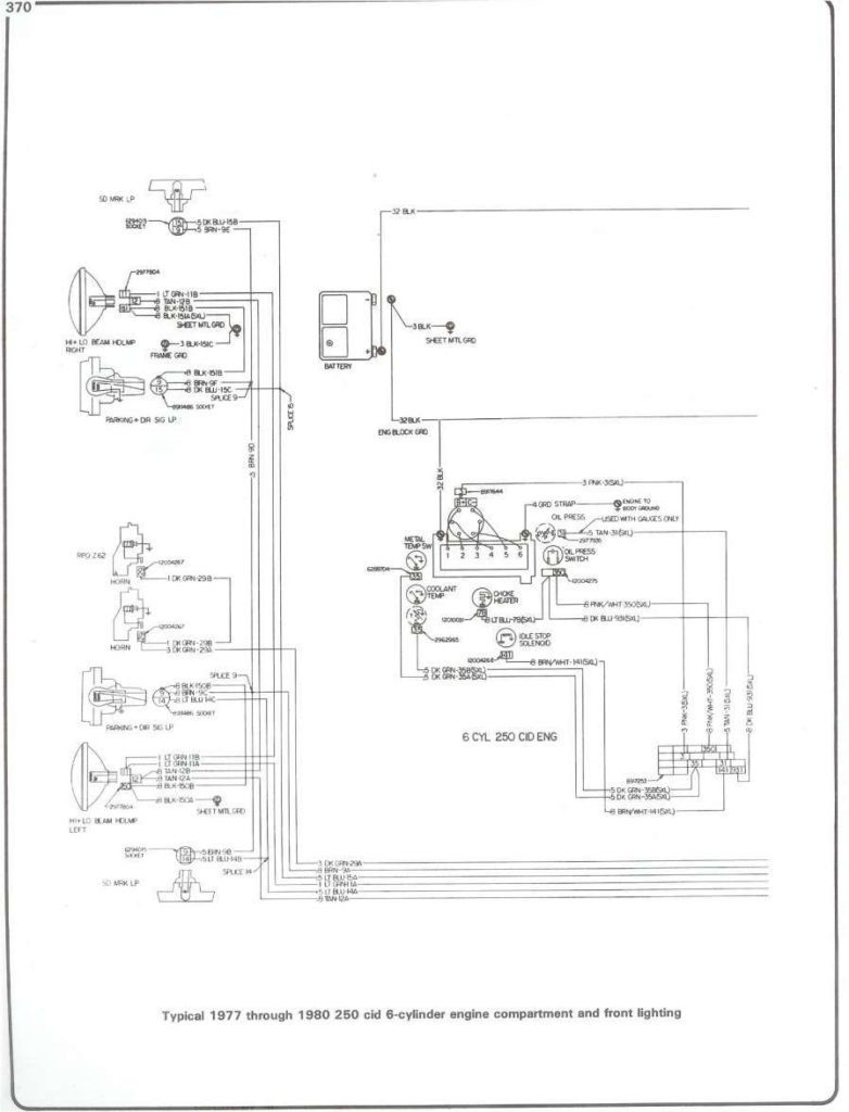
1978 Chevy Truck Ignition Switch Wiring Diagram – Let’s first examine the various terminals on the ignition switch. These terminals comprise the Ignition switch, the Coil along with the Accessory. Once we have identified the terminals that are utilized, we can begin to determine the various components of the 1978 Chevy Truck Ignition Switch Wiring Diagram. We will also discuss what functions are available for the Ignition switch and the Coil. Then, we’ll focus to the accessory terminals.
The terminals are for ignition switches.
An ignition switch has three switches. They feed the voltage of the battery to different locations. The first one is utilized to power the choke through pushing it, while the second is for the ON/OFF setting. Different manufacturers utilize their own color-coding method for different conductors that is described in a separate article. OMC follows this system. The adapter is attached to the ignition switch that allows the addition of a tachometer.
Although most ignition switch terminals are duplicated, the number may not be in line with the diagram. Check the integrity of the wires first to ensure they’re properly connected to the ignition switch. You can do this with an inexpensive multimeter. After you’re happy with the continuity of the wires, you can connect the new connector. If your vehicle has an original ignition switch supplied by the factory (or a wiring loom) The wiring loom will differ from that of the car.
The first step is to understand the distinctions between ACC and secondary outputs. The ACC and IGN terminals are the default connections for your ignition switch, and the START and IGN terminals are the primary connections to the stereo and radio. The ignition switch is responsible to turn the car’s engines on and off. Older cars are identified with the letters “ACC”, “ST”, (for individual magneto cables) at their ignition switch terminals.
Terminals for coil
The terms used to define the kind and model of an ignition coil is the primary thing. You will see several connections and terminals in a basic ignition wiring schematic that include two primary as well as two secondary. The voltage that operates on each coil is different. This is why it is essential to first check the voltage at the S1 (primary terminal). S1 should also undergo resistance tests to determine if it is a Type A or B coil.
The coil’s low-tension side should be connected at the chassis’s minus. This is the wiring diagram you will see in the diagram of wiring. The high-tension supply supplies positive directly to spark plugs. The coil’s metal body needs to connect to the chassis for suppression purposes however it isn’t electrically essential. You will also see the connections of the positive and negative coil’s terminals on the ignition wiring diagram. In certain cases scanning your local auto parts store will be able to diagnose defective ignition coils.
The black-and-white-striped wire from the harness goes to the negative terminal. The positive terminal also receives a white wire that has a black trace. The contact breaker is attached to the black wire. You can examine the connections with a paperclip to take the wires out of the housing. It’s also essential to make sure that the terminals do not bend.
Accessory terminals
Diagrams of ignition wiring depict the wires that are used to power the vehicle’s electrical supply. Each component is equipped with four distinct connections that are color coded. The red color is for accessories, yellow the battery and green the starter solenoid. The “IGN terminal lets you start the car, manage the wipers or other features that operate. This diagram demonstrates how to connect ACC and ST terminals to the rest of the components.
The terminal BAT holds the battery. The electrical system can’t start without the battery. Also, the switch won’t start without the battery. If you’re not sure the exact location where the battery in your car is situated, you can review your wiring diagram to see how to locate it. The ignition switch is connected to the battery of your car. The BAT terminal is connected with the battery.
Certain ignition switches come with the “accessory” position that allows users to control their outputs without needing to turn on the ignition. Sometimes, a customer wants to make use of the auxiliary output separately from the ignition. To allow the auxiliary output to be used, connect the connector in the same shade as the ignition. Then , connect it to the ACC end of the switch. This is an excellent option, but there’s an important distinction. Most ignition switches will be in an ACC position when the vehicle is in the ACC however, they’ll be at the START position when the car is in IGN.
Gallery of 1978 Chevy Truck Ignition Switch Wiring Diagram
Gallery of 1978 Chevy Truck Ignition Switch Wiring Diagram


