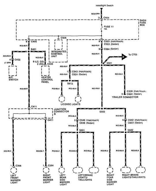
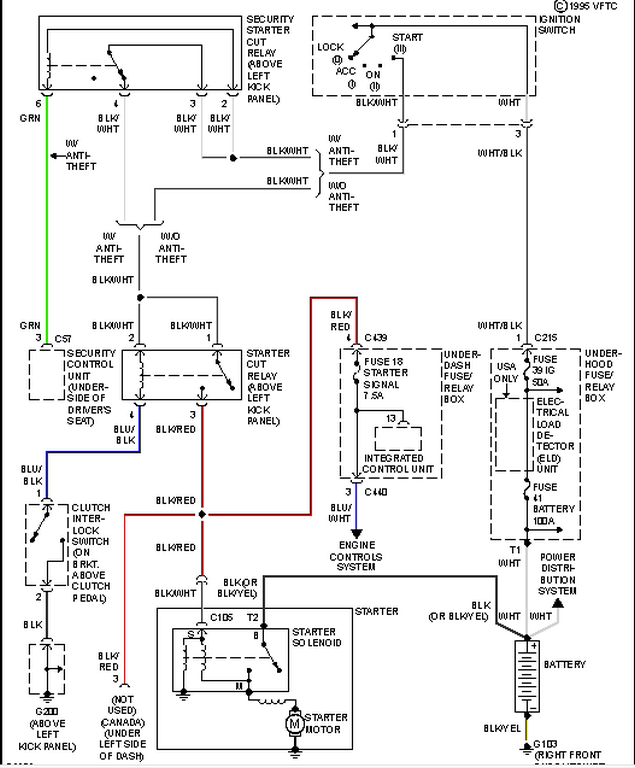
Integra Ignition Switch Wiring Diagram – In the beginning, we’ll examine the various types of terminals found in the ignition switch. These include the terminals for the Ignition switch, Coil, and Accessory. Once we know the terminals used, we can begin to determine the various components of the Integra Ignition Switch Wiring Diagram. We’ll also go over the function of the Ignition switch and Coil. Then, we will turn our attention towards the accessories terminals.
Ignition switch terminals
The ignition switch is comprised of three separate switches that feed the battery’s current to different destinations. The choke is powered by the first switch. The second switch is responsible for the ON/OFF of the ignition switch. Different manufacturers have different color-coding systems for different conductors. We will cover this in a separate article. OMC uses this system. Connectors can be attached to the ignition switch to connect a digital tachometer.
While many ignition switch terminals may not be authentic, the numbering of each may not be in line with the diagram. Check the electrical continuity to determine if they’re connected to the ignition switch correctly. A multimeter is an excellent tool to check the continuity. Once you’re satisfied with the continuity it’s time to connect the new connector. If your vehicle has an original factory-supplied ignition switch (or an electrical loom), the wiring loom might differ from that of the car.
Understanding how ACC outputs are connected to the auxiliary outputs of your car is essential. The ACC and IGN connectors are the standard connections for your ignition switch. While the START, IGN, and ACC terminals are the primary connections for radios or stereo, the START/IGN terminals are the main ones. The ignition switch is the one that controls the engine of your car. In older vehicles the ignition switch’s terminals are identified with the initials “ACC”, and “ST” (for distinct magnet wires).
Terminals for coil
Understanding the terms is the initial step in knowing what type of ignition coil you own. A basic ignition wiring layout will reveal a variety of terminals and connections. Each coil has a specific operating voltage. To determine what kind of coil you own, the first step is to determine the voltage at the S1 primary terminal. You should also check S1 for resistance in order to determine whether it is a Type A, B, or C coil.
The chassis’ negative end should be connected to to the coil’s lower-tension end. This is the ground in the ignition wiring diagram. The high-tension supply provides positively directly to spark plugs. It is required to suppress the body of the coil’s metal be connected to the chassis, however, it is not necessary. The ignition wiring diagram will also indicate the connections of the positive coil terminals. It is possible to find an issue with your ignition coil which can be identified by scanning it in an auto parts retailer.
The black-and-white-striped wire from the harness goes to the negative terminal. The positive terminal receives the white wire and the trace in black. The black wire is connected to the contact breaker. To confirm the connection, employ a paperclip, or a pencil to lift them out from the plug housing. Be sure the terminals aren’t bent.
Accessory terminals
Diagrams of ignition wiring show the various wires utilized to power the various components. In general there are four colors-coded terminals that are used for each component. The red color is for accessories, yellow is the battery, and green the starter solenoid. The “IGN” terminal allows you to start the car, manage the wipers, and any other operation features. The diagram shows how to connect ACC or ST terminals as well as the rest.
The terminal BAT is the connection to the battery. The electrical system will not start when the battery isn’t connected. A dead battery can cause the switch to stop turning on. To locate your car’s battery examine the wiring diagram. The accessory terminals of your car are connected to the battery as well as the ignition button. The BAT terminal is connected to the battery.
Some ignition switches come with an accessory position. This allows users to access their outputs from a different location without having to turn on the ignition. Some customers might want to utilize the auxiliary input separately from the ignition. To make use of the auxiliary output, connect the connector in the same colors as the ignition, and connect it to the ACC terminal on the switch. This feature is convenient however, it does have one significant distinction. Most ignition switches come with the ACC position when the car is in ACC mode and a START mode when it is in IGN.
Gallery of Integra Ignition Switch Wiring Diagram
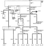
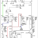
Gallery of Integra Ignition Switch Wiring Diagram


