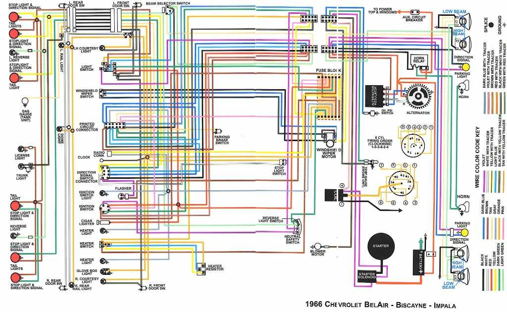
1966 Impala Ignition Switch Wiring Diagram – Let’s begin by looking at the different types of terminals on the ignition switch. These terminals comprise the Ignition switch, the Coil and the Accessory. Once we have established what these kinds of terminals are then we can identify the different parts of the 1966 Impala Ignition Switch Wiring Diagram. We’ll also discuss the function of the Ignition switch and Coil. Then, we’ll focus on the accessory terminals.
Terminals for ignition switch
There are three switches in an ignition switch that transmit the battery’s current voltage to a variety of destinations. The first switch is used to drive the choke through pushing it. Then, the third switch is used to control the ON/OFF position. Different manufacturers use different color-coding methods for different conductors. We will cover this in a different article. OMC utilizes this system. The connector allows for the attachment of a speedometer to the ignition switch.
While many ignition switch terminals don’t appear in their original configuration, the numbering may not match the diagram. You should first check the continuity of the wires to see if they are plugged into the ignition switch correctly. This can be checked using a cheap multimeter. When you’re satisfied that all wires are running in good harmony and you are able to connect the new connector. If your car has an original factory-supplied ignition switch (or wiring loom) the wiring loom may differ from that in your car.
Before you can connect the ACC outputs to your car’s auxiliary outputs It is essential to know the fundamentals of these connections. The ACC and IGN terminals are the default connections on your ignition switch, and the START and IGN terminals are the principal connections for the stereo and radio. The ignition switch is accountable to turn the engine of your car on and off. The ignition switch terminals on older vehicles are marked with the letters “ACC” as well as “ST” (for the individual magneto wires).
Terminals for coil
Understanding the terms is the initial step in finding out what kind of ignition coil you’ve got. An ignition wiring diagram will display a range of terminals and connections, which include two primary terminals and two secondary. The coils have a specific operating voltage, and the first method of determining what type you’re using is to test the voltage of S1 the primary terminal. S1 must also be subjected to resistance testing to determine whether it’s a Type A or B coil.
The negative end of the chassis end should be connected to the coil’s low-tension side. This is what’s called the ground in the ignition wiring diagram. The high-tension side supplies the positive power direct to the spark plugs. For suppression purposes the coil’s body metal must be connected with the chassis. This is not necessary for electrical use. You will also see the connections of the positive and the negative coil terminals on the ignition wiring diagram. In certain instances it is recommended to conduct a scan at your local auto parts store will be able to diagnose malfunctioning ignition coils.
The black-and-white-striped wire from the harness goes to the negative terminal. The white wire is the other one. It is black with a trace, and it goes to the positive terminal. The black wire connects to the contactbreaker. If you’re not sure about the connections of the twowires, use the clip of a paperclip to remove them from the housing of the plug. Make sure that the terminals don’t bend.
Accessory terminals
Diagrams of the ignition wiring illustrate the wires that supply power to different parts of the vehicle. There are usually four different colored terminals for each component. Red refers to accessories, yellow the battery, and green for the starter solenoid. The “IGN” terminal is used to turn on the vehicle and control the wipers as well as other operational features. The diagram illustrates how you can connect ACC or ST terminals as well as the rest.
The battery is attached to the terminal whose name is BAT. The electrical system will not start without the battery. Additionally the switch won’t come on. You can refer to your wiring diagram if you’re uncertain about where the car’s batteries are located. The ignition switch is connected to the car’s battery. The BAT connector is connected to the battery.
Some ignition switches feature an additional “accessory” position, in which users can control their outputs with no ignition. Customers may want to utilize the auxiliary output in addition to the ignition. Use the additional output by connecting it to an ACC terminal on your switch that has the same color. This feature is convenient, but it has one significant difference. Some ignition switches are configured to be in an ACC position once the car has been moved into the ACC position. They will also be in START mode when the vehicle has entered the IGN position.
Gallery of 1966 Impala Ignition Switch Wiring Diagram
Gallery of 1966 Impala Ignition Switch Wiring Diagram


