1995 Chevy 1500 Ignition Switch Wiring Diagram – Let’s start by looking at the various types terminals found on an ignition switch. These terminals are for the Ignition button, Coil and Accessory. Once we understand the function of each kind of terminal, we are able to identify the parts of the ignition wiring. Then, we will discuss the functions and the Coil. We will then focus on the accessories terminals.
Terminals for ignition switch
An ignition switch is comprised of three switches. They transmit the battery’s voltage to many different places. The first switch supplies the choke with power when pushed, and the second is the position of the ignition switch’s ON/OFF. Different manufacturers utilize their own color-coding method for the different conductors, which is explained in a different article. OMC uses this method. The connector allows for the attachment of a speedometer the ignition switch.
While the majority of ignition switch terminals don’t appear in their original configuration The numbering might not match that of the diagram. Before plugging into the ignition switch be sure to test the continuity. This can be accomplished with a simple multimeter. After you’re sure that all wires are in good continuity, you can attach the new connector. If your car has an installed ignition switch, the wiring diagram will differ.
Knowing how the ACC outputs are connected to the auxiliary outputs of your vehicle is crucial. The ACC and IGN terminals are the default connections for the ignition switch. the START and IGN terminals are the principal connections for stereo and radio. The ignition switch is the one that controls the engine of your car. The terminals for the ignition switch on older vehicles are marked with the letters “ACC” as well as “ST” (for each magneto wires).
Terminals for Coil
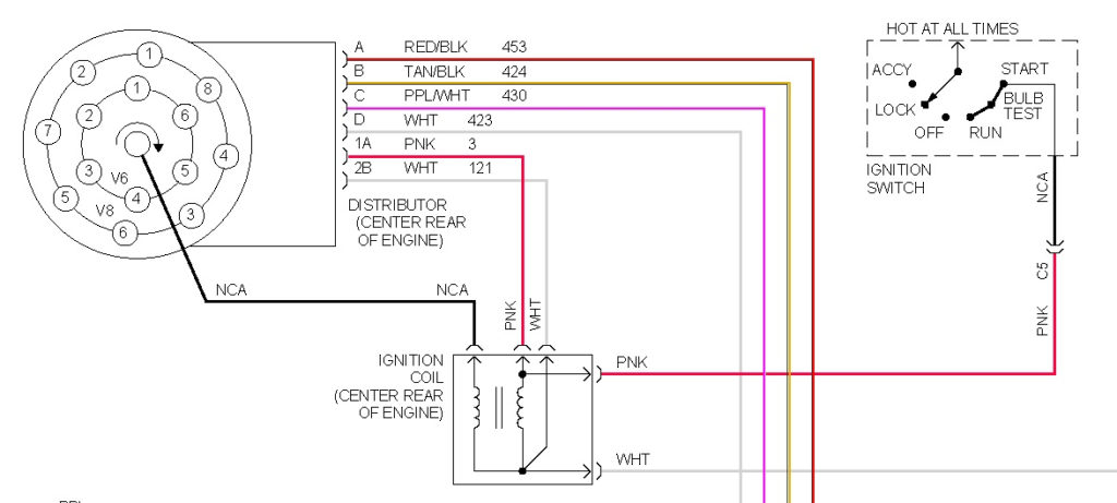
The first step to determine the type of ignition coil is to know the terms employed. In a simple ignition wiring diagram, you will see a number of different terminals and connections, including two primary and two secondary. The operating voltage of each coil is different. It is important to first test the voltage at S1 (primary terminal). S1 must be checked for resistance to determine if the coil belongs to Type A, B, or C.
The coil’s low-tension end must be connected to the chassis positively. This is exactly what you can find in the diagram of wiring. The high-tension side delivers positively directly to the spark plugs. It is necessary to suppress the coil’s metallic body be connected to its chassis however, it is not necessary. The ignition wiring diagram will also show you the connection of the positive and negative coil terminals. Sometimes, a visit to an auto parts shop can identify a problem with the ignition wire.
The black-and-white-striped wire from the harness goes to the negative terminal. The white wire also has a black trace on it, and connects to the positive terminal. The black wire is connected to the contact breaker. You can examine the connections with a pencil to remove the wires of the housing. It is also important to see that the terminals aren’t bent.
Accessory terminals
Diagrams of ignition wiring illustrate the wires that are used to power the vehicle’s electrical supply. There are typically four colored terminals that correspond to the component. Red is used for accessories while yellow is the battery, while green is for the solenoid for starters. The “IGN” terminal allows you to start the car, manage the wipers, and any other operation features. The diagram shows the connection between the ACCand ST terminals.
The terminal BAT connects the battery to the charger. The electrical system will not start if the battery isn’t connected. Furthermore the switch isn’t turned on. You can refer to your wiring diagram if uncertain about where the car’s batteries are located. The ignition switch is connected to the car’s battery. The BAT terminal is connected to the battery.
Certain ignition switches have an additional “accessory” position, in which users can control their outputs without the ignition. Customers sometimes want an auxiliary output that can be used independently from the ignition. In order for the auxiliary output be used, connect the connector in the same shade as that of the ignition. Connect it to the ACC end of the switch. While this is an excellent option, there’s an important difference. Many ignition switches can be programmed to have an ACC position once the car has been moved into the ACC position. They’ll also be in the START mode after the vehicle has been entered the IGN position.
Gallery of 1995 Chevy 1500 Ignition Switch Wiring Diagram
Gallery of 1995 Chevy 1500 Ignition Switch Wiring Diagram


