1964 Impala Ignition Switch Wiring Diagram – In the beginning, we’ll take a look at the various kinds of terminals on the ignition switch. They include terminals that are used for Coil, Ignition Switch, and Accessory. Once we understand the function of each terminal, it is possible to determine the components of the ignition wiring. We’ll also discuss the roles of both the Ignition Switch and Coil. We’ll then turn our attention on the accessory terminals.
Ignition switch terminals
Three switches are found in an ignition switch. Each of the three switches transmits the battery’s current to various places. The ON/OFF setting of the switch that controls the ignition is managed by the third switch, which delivers power to the choke when it’s pushed. Different manufacturers have distinct colour-coding systems that correspond to the conductors. OMC utilizes this system. The ignition switch comes with a connector for adding a Tachometer.
Although the majority of ignition switch terminals don’t have an original number, they might be equipped with a different number. Check the continuity of each wire to ensure they are correctly plugged into the ignition switches. A cheap multimeter can help you do this. Once you’re satisfied about the continuity of your wires, you will be able to install the new connector. If your car has an original factory-supplied ignition switch (or an electrical loom) The wiring loom will differ from that in your car.
It is essential to know how the ACC outputs and auxiliary outputs function to join them. The ACC/IGN connections function as the default connections on the ignition switch. The START/IGN connections connect to the radio or stereo. The ignition switch acts as the engine’s switch to turn off or on. Older vehicles are identified with the letters “ACC”, “ST”, (for individual magneto cables) on their ignition switch terminals.
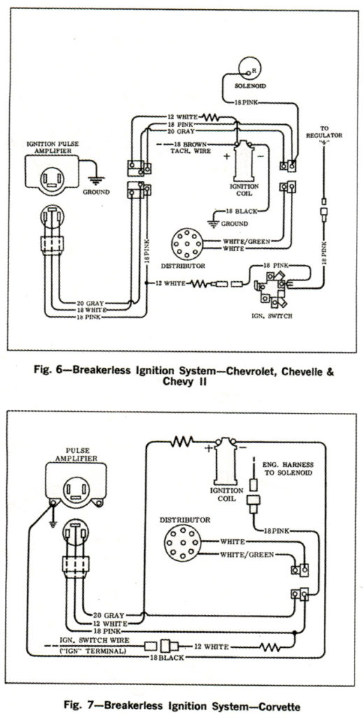
Coil terminals
Understanding the terminology utilized is the first step to finding out the right type of ignition coil. In a basic diagram of the wiring for ignition you’ll see a number of different connections and terminals, which include two primary and two secondary. It is essential to identify the type of coil that you own by examining the voltage at the primary terminal S1. Also, you should examine S1 for resistance in order to determine if it’s an A, B, or C coil.
The coil’s low-tension component is to be connected to the chassis’ positive. This is the ground of the ignition wiring. The high-tension part is a positive connection to the sparkplugs. It is essential to suppress the metallic body of the coil is connected to its chassis but not essential. The ignition wiring diagram will also indicate the connection of the positive coil terminals. In some cases scanning your local auto parts shop will be able to diagnose defective ignition coils.
The black-and-white-striped wire from the harness goes to the negative terminal. The white wire has a black color and goes to the negative terminal. The black wire goes to the contact breaker. To verify the connection, make use of a paperclip or pencil to lift them out of the plug housing. You should also check to see that the terminals aren’t bent.
Accessory Terminals
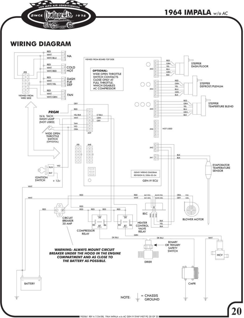
The ignition wiring diagrams illustrate the different wires that are used to power various components of the car. There are generally four colors-coded terminus of each part. For accessories, red stands for starter solenoid, blue for battery, and blue for accessory. The “IGN” terminal can be used to start the vehicle and control the wipers, as well as other operating functions. The diagram shows how to connect the ACC and ST terminals to the rest of the components.
The terminal called BAT is the location where the battery is. The electrical system will not start when the battery isn’t connected. Also, the switch won’t turn on without the battery. You can view your wiring diagram to determine the location of your car’s batteries. placed. The ignition switch is connected to the battery of your car. The BAT terminal is connected to the battery.
Some ignition switches feature an independent “accessory” position, in which users can control their outputs with no ignition. Sometimes, users want to use an auxiliary output that is independent of the ignition. In order for the auxiliary output be used, plug in the connector with the same color as the ignition. Then connect it with the ACC end of the switch. This is a useful feature, however there’s an important difference. Most ignition switches will have an ACC position when the vehicle is in ACC however they’ll be at the START position if the vehicle is IGN.
Gallery of 1964 Impala Ignition Switch Wiring Diagram
Gallery of 1964 Impala Ignition Switch Wiring Diagram


