Electronic 12 Volt Ignition Coil Wiring Diagram – In the beginning, we’ll look at the different types of terminals found in the ignition switch. These terminals serve for the Ignition button, Coil and Accessory. Once we know which terminals are used then we can determine the various components of the Electronic 12 Volt Ignition Coil Wiring Diagram. We’ll also go over the roles of the Ignition switch and Coil. Following that, we’ll shift our attention to the Accessory terminals.
Terminals for ignition switches
An ignition switch is made up of three switches. These are responsible for feeding the battery’s power to various destinations. The first switch is utilized to drive the choke by pushing it, while the third switch is used to control the ON/OFF setting. Each manufacturer has its unique color-coding system, which we’ll discuss in a subsequent article. OMC utilizes this method. The ignition switch is also equipped with a connector for adding the timer.
While the majority of ignition switch terminals don’t carry an original number, they might be equipped with a different number. First, check the continuity of all wires to ensure they are correctly plugged into the ignition switches. This can be accomplished using a cheap multimeter. After you’re satisfied with the integrity of the wires it is time to connect the new connector. The wiring loom for the ignition switch factory-supplied will be different than the one that you have in your car.
It is essential to know the ways in which the ACC outputs and auxiliary outputs function in order to join them. The ACC, IGN and START terminals are your default connections to the ignition switch. They are also the primary connections to the radio and stereo. The ignition switch operates the engine’s switch to turn off or on. The terminals of older cars ignition switches are identified by “ACC” as well as ST (for specific magneto wires).
Terminals for coil
To determine the type of ignition coil, the initial step is to learn the terminology. A basic ignition wiring diagram will reveal a variety of terminals and connections, which include two primary terminals and two secondary. The operating voltage of each coil is different. Therefore, it is important to first test the voltage at the S1 (primary terminal). S1 must be examined for resistance to determine if the coil is type A, B or C.
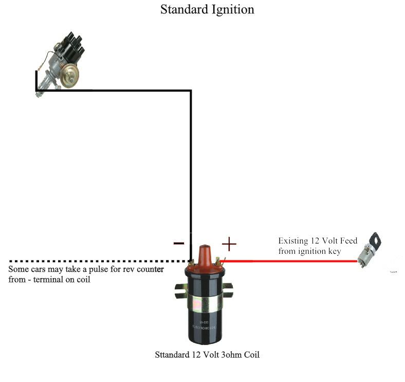
The negative of the chassis must be connected to the side of low-tension. This is the base of the wiring for ignition. The high tension side provides positively directly to the spark plugs. The metal body of the coil needs to be connected to the chassis for suppression purposes however it isn’t electrically necessary. The diagram of the ignition wiring will also demonstrate the connection of the negative and positive coil’s terminals. In some instances, you’ll find that an ignition coil that is malfunctioning is easily identified with scans in an auto parts store.
The black-and-white-striped wire from the harness goes to the negative terminal. The white wire is the other one. It has a black trace on it and connects to the positive terminal. The black wire connects to the contact breaker. You can examine the connections with a paperclip to pull the wires out from the housing. Also, make sure that the connections are not bent.
Accessory terminals
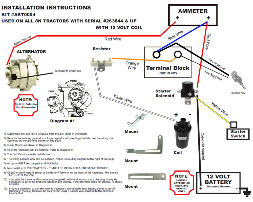
Diagrams of ignition wiring depict the wires used in the vehicle’s power supply. Typically there are four colors-coded terminals that are used for each component. The red color is used for accessories, yellow is for the battery, and green is the solenoid for starters. The “IGN” terminal is used to start the vehicle and control the wipers and other operating features. The below diagram illustrates how to connect the ACC terminal as well as the ST terminals to various components.
The terminal called BAT is the place where the battery is. The battery is essential for the electrical system to start. Also, the switch won’t turn on without the battery. The wiring diagram will show you where to find the battery in your car. The accessory terminals of your car are connected to the battery and the ignition button. The BAT terminal is connected to the battery.
Certain ignition switches have a separate “accessory” position, in which users can manage their outputs with no ignition. Sometimes, customers wish to use the auxiliary output separately from the ignition. To allow the auxiliary output to be used, connect the connector with the same color as that of the ignition. Then , connect it to the ACC end of the switch. Although this is a useful feature, there is one crucial distinction. Some ignition switches are configured to be in an ACC location when the car has been moved into the ACC position. They’ll also be in the START mode when the vehicle has moved into the IGN position.
Gallery of Electronic 12 Volt Ignition Coil Wiring Diagram
Gallery of Electronic 12 Volt Ignition Coil Wiring Diagram


