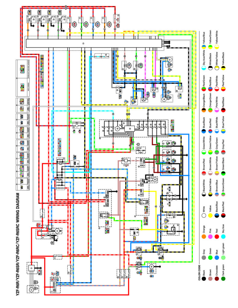
Yamaha R1 Ignition Wiring Diagram – First, we will look at the different types of terminals found on the ignition switch. These include the terminals for the Ignition switch, Coil, and Accessory. Once we know what these terminals do and what they do, we can then identify the different parts in the ignition wiring. In addition, we will discuss the roles of both the Ignition Switch and Coil. Following that, we will proceed to the Accessory Terminals.
Terminals for ignition switches
An ignition switch is composed of three switches. They are the ones that supply the battery’s power to several places. The choke is powered by the first switch. The second switch controls the ON/OFF of the ignition switch. Different manufacturers have different color-coding systems to identify different conductors. This will be covered in a separate article. OMC utilizes this method. The ignition switch also includes an option to connect an tachometer.
While many ignition switch terminals may not be authentic, the numbering of each may not match the diagram. Before you plug into the ignition switch, ensure that you check the continuity. A multimeter is an excellent tool to check the continuity. When you’re satisfied that the wires are in good order and you are able to connect the new connector. If you have a factory-supplied ignition switch the wiring loom will be different from the one in your car.
You must first understand the way that ACC outputs and auxiliary outputs function to connect them. The ACC, IGN and START terminals are your default connections to the ignition switch. They also serve as the primary connections to the radio and stereo. The ignition switch is the one that turns the engine of your car on and off. On older cars the ignition switch’s terminals are identified with the initials “ACC” and “ST” (for distinct magnet wires).
Terminals for coil
To identify the kind of ignition coil, the first step is to understand the terminology. The fundamental diagram of ignition wiring depicts various connections and terminals. There are two primary and one secondary. You must determine the type of coil that you own by examining the voltage at the primary terminal S1. To determine if the coil is an A, C, or B coil you must also test the resistance on S1’s.
The coil’s low-tension end must be connected to the chassis positive. This is also the ground in the diagram of ignition wiring. The high tension part supplies positive power directly to the spark plugs. To prevent noise, the coil’s metal body is required to be connected to the chassis. However, it is not necessary to electrically connect. The wiring diagram of the ignition will demonstrate how to connect the terminals of either the positive or negative coils. Sometimes, a malfunctioning ignition coil can be identified through a scan performed at an auto parts shop.
The black-and-white-striped wire from the harness goes to the negative terminal. The other white wire is black-colored and connects to the terminal opposite. The black wire connects to the contact breaker. If you’re not certain about the connections of both, you can use a paper clip to remove them from the plug housing. Check that the terminals aren’t bent.
Accessory terminals
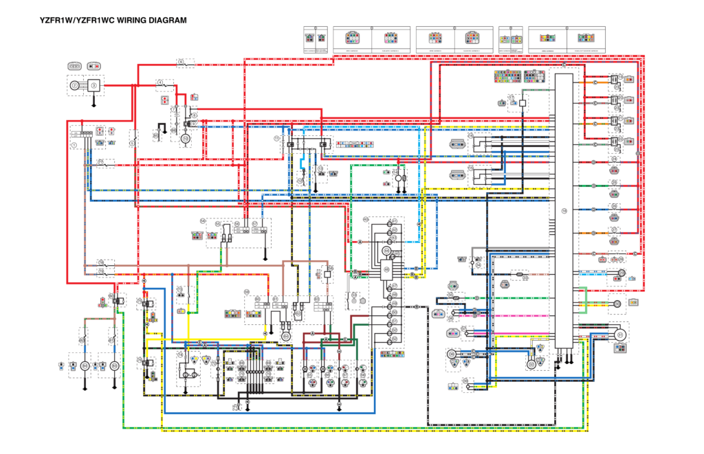
The diagrams for ignition wiring show the wiring used to power the vehicle’s electrical supply. Typically there are four color-coded terminals for each component. Red is used to indicate accessories, yellow is the battery and green the starter solenoid. The “IGN terminal” is used to power the wipers along with other operational functions. The diagram illustrates the connection of the ACCand ST terminals.
The battery is connected to the terminal named BAT. The battery is vital to allow the electrical system to start. Additionally, the switch won’t begin to turn on. A wiring diagram can show you the location of your car’s battery. The ignition switch and the battery are connected by the accessory terminals. The BAT terminal is connected to the battery.
Some ignition switches feature an additional “accessory” location, which allows users can control their outputs without using the ignition. Sometimes, a customer wants to use the auxiliary output separately from the ignition. The auxiliary output can be used by wiring the connector with the same colors as your ignition and attaching it to the ACC terminal of the switch. Although this is a fantastic feature, there’s something you should know. Many ignition switches can be set to have an ACC location when the car has been moved into the ACC position. They’ll also be in the START position once the vehicle is entered the IGN position.
Gallery of Yamaha R1 Ignition Wiring Diagram
Gallery of Yamaha R1 Ignition Wiring Diagram


