Ignition Coil Wiring Diagram With Resistor – We will first look at the various types of terminals that are used on the ignition switch. These are the terminals used that are used for Coil, Ignition Switch, and Accessory. Once we know the purpose of these terminals and what they do, we can then be able to identify the various parts of the ignition wiring. We’ll also discuss the functions of both the Ignition Switch and the Coil. Then, we’ll focus to the accessory terminals.
The terminals are for ignition switches.

Three switches are found in an ignition switch. Each of these three switches transmits the battery’s current to several different locations. The first switch powers the choke. The third switch regulates the ON/OFF switch of the ignition switch. Every manufacturer has its individual color-coding system that we will discuss in another article. OMC follows this scheme. An additional connector is included inside the ignition switch for connecting the to a tachometer.
Even though most ignition switch terminals don’t carry an original number, they may have a different number. Before you plug into the ignition switch, be sure to test the continuity. You can check this using a simple multimeter. After you’re sure that the wires are in good continuity then you can connect the new connector. The wiring loom of a factory-supplied ignition system switch is distinct.
Understanding how ACC outputs connect to the auxiliary outputs in your car is vital. The ACC and IGN connectors are the standard connections of your ignition switch. While the START, IGN, and ACC terminals are primary connections to the radio or stereo, the START/IGN terminals are the primary ones. The ignition switch operates the engine’s on/off button. The terminals of the ignition switch on older cars are identified with the letters “ACC” and “ST” (for each magneto wires).
Terminals for coil
The language used to decide the type and model of the ignition coil is the primary thing. An understanding of the basic wiring diagram for ignition will provide you with a range of connections and terminals. The voltage that operates on every coil is different. This is why it is important to first test the voltage at S1 (primary terminal). S1 should also undergo resistance testing to determine if it is a Type A or B coil.
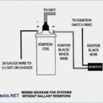
The negative end of the chassis end should be connected to the coil’s low-tension side. This is also the ground in an ignition wiring diagram. The high tension side supplies positive power directly to the spark plugs. It is essential for the purpose of suppression that the body of the coil’s metal be connected to the chassis, but not essential. The diagram of the ignition wiring will also reveal how to connect the positive and negative coil terminals. Sometimes, a malfunctioning ignition coil can be identified by a scan done in an auto parts shop.
The black-and-white-striped wire from the harness goes to the negative terminal. The positive terminal also receives a white wire that is black in its trace. The black wire is connected to the contact breaker. If you’re not sure about the connections between both, you can use the clip of a paperclip to remove them from the plug housing. Be sure the terminals do not bend.
Accessory terminals

The ignition wiring diagrams illustrate the various wires that power the various components of the vehicle. Each component has four distinct connections that are color coded. The accessories are red, the battery is yellow, and the starter solenoid green. The “IGN terminal” is used to power the wipers and other operating features. The diagram shows how you can connect the ACC and ST terminals to the other components.
The battery is attached to the terminal named BAT. The battery is necessary to allow the electrical system to start. Additionally, the switch won’t start. If you don’t know the location of your car’s battery situated, you can look at the wiring diagram of your car to determine the best way to find it. The accessory terminals of your vehicle are connected to the battery and the ignition switch. The BAT terminal connects to the battery.
Certain ignition switches have an accessory position where users can adjust their outputs and control them without having to turn on the ignition. Sometimes, a customer wants to make use of an auxiliary output that is separate from the ignition. To allow the auxiliary output to be used, plug in the connector with the same shade as that of the ignition. Then , connect it to the ACC end of the switch. This feature of convenience is fantastic however, there’s one differentiator. Most ignition switches come with the ACC position when your car is in the ACC mode and a START position when you are in IGN.
Gallery of Ignition Coil Wiring Diagram With Resistor
Gallery of Ignition Coil Wiring Diagram With Resistor


