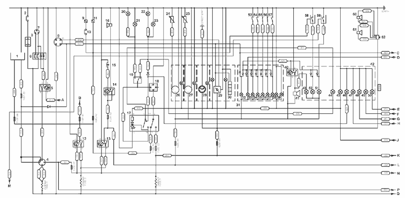
Jcb Ignition Switch Wiring Diagram – In the beginning, we’ll take a look at the various kinds of terminals found in the ignition switch. These terminals are for the Ignition button, Coil and Accessory. After we’ve identified what these terminals do and what they do, we can then identify the different parts in the ignition wiring. We’ll also go over what functions are available for the Ignition switch as well as the Coil. After that, we’ll turn our attention to the Accessory terminals.
Terminals for ignition switch
An ignition switch contains three different switches that direct the battery’s power to various destinations. The first switch is the one that supplies power to the choke while the second switch controls the status of the ignition switch. Different manufacturers have different colour-coding systems that correspond to the conductors. OMC utilizes the same system. A connector can be added to the ignition switch to include a digital tachometer.
While many ignition switch terminals may not be original, the numbers of each may not be in line with the diagram. Check the electrical continuity to see if they are connected to the ignition switch correctly. A multimeter that is inexpensive can assist you in this. When you’re satisfied that all wires are in good order, you can attach the new connector. The wiring loom for an ignition switch that’s supplied by the factory will be different from the one that you have in your vehicle.
It is important to know the differences between ACC and secondary outputs. The ACC/IGN terminals function as the default connections for the ignition switch. The START/IGN terminals are connected to the stereo or radio. The ignition switch controls the car’s engine. On older cars the terminals of the ignition switch are marked with the alphabets “ACC”, and “ST” (for the individual magnetic wires).
Terminals for coil
The first step to determine the kind of ignition coil is to know the terms employed. An understanding of the basic wiring diagram for ignition will reveal a variety of terminals and connections. Each coil is operating at a certain voltage. The first step to determine which kind you’re dealing with is to test the voltage of S1 or the primary terminal. S1 should also undergo resistance testing to determine if it are an A or B coil.
The low-tension end of the coil needs to be connected to the chassis the negative. This is what’s called the ground in the ignition wiring diagram. The high-tension side delivers positively directly to the spark plugs. It is required for suppression purposes that the coil’s metallic body be connected to its chassis, however it isn’t essential. The wiring diagram of the ignition will demonstrate how to connect the terminals of either the negative or positive coils. In some instances it is possible to find the ignition coil is damaged and is identified by scanning at an auto parts shop.
The black-and-white-striped wire from the harness goes to the negative terminal. The positive terminal receives the other white wire and the trace in black. The black wire connects to the contact breaker. To test the wires’ connections, use a paperclip to remove them from the housing. Be sure that the terminals aren’t bent.
Accessory terminals
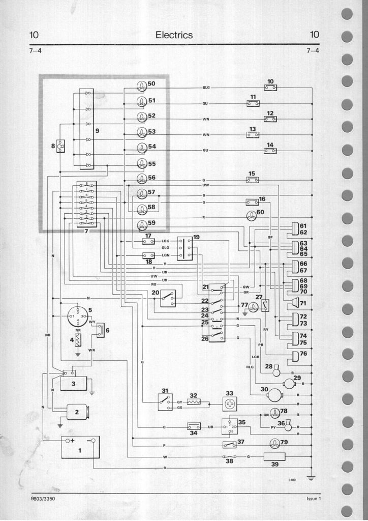
Diagrams of ignition wiring illustrate the wires that power various parts of the car. In general there are four distinct colored terminals for each part. Red is used to indicate accessories, yellow is the battery, and green is the starter solenoid. The “IGN terminal is used for starting the car, operating the wipers and various other functions. The diagram illustrates how to connect ACC or ST terminals as well as the rest.
The terminal referred to as BAT is the location where the battery is. The electrical system will not start in the event that the battery isn’t connected. The switch won’t turn off if the battery isn’t present. To locate your car’s battery examine the wiring diagram. The ignition switch is linked to the car’s battery. The BAT terminal is connected to the battery.
Certain ignition switches have an additional position. This allows users to connect their outputs to a different location without having to turn on the ignition. Sometimes, customers may wish to use the auxiliary output separately from the ignition. You can utilize the secondary input by connecting it to the ACC terminal. This is an excellent feature, however there’s one important difference. The majority of ignition switches are configured to display an ACC status when the car is at either the ACC or START position.
Gallery of Jcb Ignition Switch Wiring Diagram
Gallery of Jcb Ignition Switch Wiring Diagram


