Honda Gx390 Ignition Wiring Diagram – Let’s begin by examining the different types and functions of the terminals found on the ignition switches. These are the terminals that connect the Ignition, Coil, or Accessory. Once we know the purpose of each kind of terminal, it is possible to identify the various components of the ignition wiring. We will also talk about the functions as well as the Coil. We will then turn our attention towards the accessories terminals.
The terminals of the ignition switch
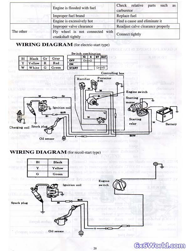
An ignition switch has three switches. They supply the battery’s voltage to different places. The first switch is utilized to power the choke through pushing it. Then, the second is for the ON/OFF setting. Different manufacturers use different color-coding methods for different conductors. We will cover this in a different article. OMC utilizes this method. The ignition switch comes with an option to connect the tachometer.
While many ignition switch terminals might not be original, the numbering of each may not be in line with the diagram. Before plugging into the ignition switch, ensure that you check the continuity. This can be done using a cheap multimeter. When you’re happy with the quality of the connection, you can place the new connector. If your vehicle is equipped with an ignition switch that is installed, the wiring diagram will differ.
Knowing how the ACC outputs connect to the other outputs in your car is essential. The ACC/IGN connections function as the default connections for the ignition switch. The START/IGN connections connect to the radio or stereo. The ignition switch is accountable to turn the engine of your car on and off. The terminals for the ignition switch on older vehicles are marked with the initials “ACC” as well as “ST” (for each magneto wires).
Terminals for coil
The first step in determining the kind of ignition coil is to understand the terminology that is used. There are a variety of connections and terminals on the basic wiring diagram for ignition that include two primary as well as two secondary. Each coil is operating at a certain voltage. The first step in determining which type you’re dealing with is to test the voltage on S1, or the primary terminal. S1 must also be inspected for resistance in order to identify if the coil is a Type B, B or A coil.
The chassis’ negative end should be connected to connect the coil’s low-tension side. This is what’s called the ground on the diagram of ignition wiring. The high-tension part supplies positive direct to the sparkplugs. For suppression purposes, the coil’s metal body is required to be connected to the chassis. But, it’s not necessary to connect the coil electrically. The wiring diagram of the ignition will demonstrate how to connect the terminals of the positive and negative coils. In certain instances, you’ll find that an ignition coil that is malfunctioning can be diagnosed with scans in an auto parts store.
The black-and-white-striped wire from the harness goes to the negative terminal. The positive terminal receives the other white wire and a trace in black. The black wire connects to the contact breaker. To verify the connections, make use of a paperclip or pencil to lift them out from the plug housing. You should also check to see that the terminals are not bent.
Accessory terminals
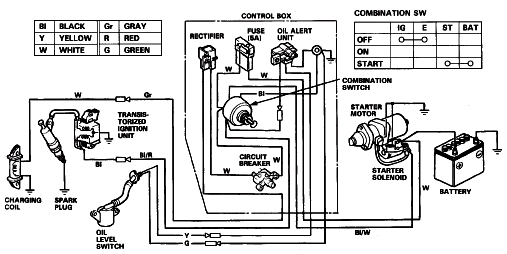
The diagrams for ignition wiring illustrate the wires that are used in the power supply of the vehicle. There are usually four colored terminals that correspond to the respective component. For accessories, red is the starter solenoid’s color, yellow is for battery, and blue for accessories. The “IGN terminal” is used to provide power to the wipers and other operating features. The diagram illustrates the connection between the ACC- and ST terminals.
The terminal BAT connects the battery to the charger. The electrical system can’t begin without the battery. A dead battery can cause the switch to not turn on. You may refer to the wiring diagram if you are uncertain about where the car’s batteries are located. The ignition switch is linked to the car’s battery. The BAT connector is connected to the battery.
Certain ignition switches have an accessory position. This allows users to access their outputs from a different location without having to turn on the ignition. Users may wish to use the auxiliary output separately from the ignition. You can use the auxiliary input by connecting it to the ACC terminal. This is a great feature, however there’s an important distinction. The majority of ignition switches are designed to have an ACC status when the car’s at the ACC or START position.
Gallery of Honda Gx390 Ignition Wiring Diagram
Gallery of Honda Gx390 Ignition Wiring Diagram


