1975 Chevy Ignition Wiring Diagram – We will first take a look at the different kinds of terminals that are used on the ignition switch. They include terminals for the Ignition switch, Coil, and Accessory. Once we’ve established the purpose of these terminals, it is possible to identify the various parts of the ignition wiring. In addition, we will discuss the roles of both the Ignition Switch and the Coil. We’ll then turn our attention to the accessory terminals.
Terminals for ignition switch
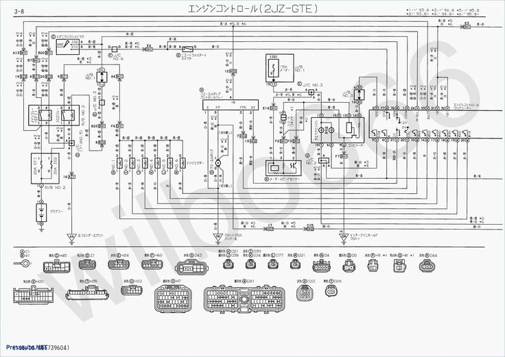
An ignition switch has three switches. They feed the battery’s voltage to many different locations. The first one supplies the choke with power when pushed, and the second is the switch that controls the ignition’s ON/OFF positions. Different manufacturers have different color-coding schemes for different conductors. We’ll discuss this in a separate article. OMC utilizes the same system. This connector allows the connection of a speedometer to the ignition switch.
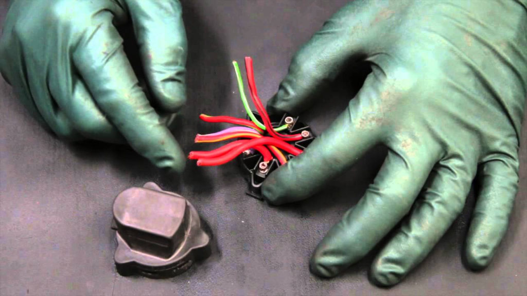
Although the majority of ignition switch terminals don’t have the original design however, the numbers may not match the diagram. The first step is to check the continuity of all wires to make sure they’re properly plugged into the ignition switches. This can be checked using a cheap multimeter. After you’re satisfied with the continuity of the wires, you can connect the new connector. If you’re using an ignition switch supplied by the manufacturer the wiring loom will be different from that in your car.
It is important to understand the ways in which the ACC outputs and auxiliary outputs function in order to connect them. The ACC terminals as well as the IGN terminals serve as the default connections to your ignition switch. The START and IGN connections are the main connections for radio and stereo. The ignition switch turns the engine of your car ON and OFF. The ignition switch terminals on older cars are labeled with the letters “ACC” and “ST” (for the individual magneto wires).
Terminals for coil
The first step in determining the kind of ignition coil is to understand the terminology used. An ignition wiring diagram will reveal a variety of connections and terminals, which include two primary terminals and two secondary. The voltage that operates on each coil differs. Therefore, it is essential to first check the voltage at the S1 (primary terminal). S1 must also go through resistance testing to determine if it is a Type A or B coil.
The coil’s low-tension side should be connected to the chassis’ plus. It is also the ground for the diagram of ignition wiring. The high-tension supply delivers the spark plugs with positive electricity directly. The metal body of the coil needs to connect to the chassis to prevent it from being smothered however it isn’t electrically essential. A wiring diagram can illustrate the connection between the positive and negative coils. In certain instances scanning the local auto parts store will help identify defective ignition coils.
The black-and-white-striped wire from the harness goes to the negative terminal. The positive terminal is connected to the white wire with the trace of black. The black wire connects to the contactbreaker. To verify the connections, use a paperclip or a pencil to remove them from the plug housing. Also, ensure that the terminals are not bent.
Accessory terminals
The diagrams for ignition wiring illustrate the wires used in the power supply of the vehicle. There are generally four colored terminus lines for each component. The red color represents accessories, yellow for the battery and green is for the solenoid for starters. The “IGN” terminal is used to turn on the car, operate the wipers, as well as other features. This diagram shows how you can connect ACC and ST terminals with the other components.
The terminal BAT connects the battery to the charger. The battery is necessary for the electrical system to get started. In addition, the switch doesn’t turn on. A wiring diagram can inform you where to find the battery of your car. The accessory terminals in your car are connected to the ignition switch, as well as the battery. The BAT terminal is connected with the battery.
Some ignition switches come with an accessory position. It allows users to access their outputs from a different place without having to turn on the ignition. Some customers might want to use the auxiliary output separately from the ignition. The auxiliary output could be connected by wiring the connector in the same color as your ignition, and then attaching it to the ACC terminal of the switch. While this is an excellent option, there’s a thing you should know. Most ignition switches come with an ACC position when the car is in the ACC mode and a START mode when it is in IGN.
Gallery of 1975 Chevy Ignition Wiring Diagram
Gallery of 1975 Chevy Ignition Wiring Diagram


