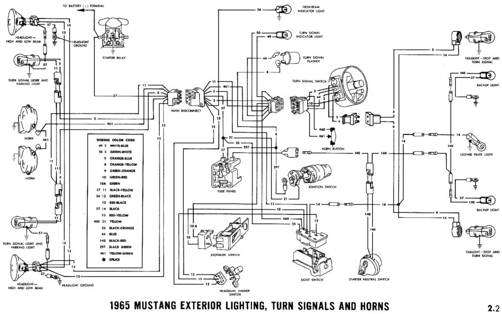
1967 Ford Galaxie Ignition Switch Wiring Diagram – First, let’s examine the various terminals that are used in the ignition switch. These are the terminals for the Ignition, Coil, or Accessory. Once we have identified what these terminals do then we can determine the various components in the ignition wiring. We will also cover the roles of both the Ignition Switch and the Coil. After that, we’ll turn our attention to Accessory terminals.
Ignition switch terminals
An ignition switch is comprised of three switches. They supply the battery’s voltage to different locations. The first switch is the one that supplies power to the choke and the third switch toggles the status of the ignition switch. Different manufacturers use different colour-coding systems that correspond to the conductors. OMC utilizes this system. The adapter is attached to the ignition switch, allowing the addition of a tachometer.
While the majority of ignition switch terminals don’t come in original form however, the numbers may not match the diagram. Check the continuity of all the wires to ensure they are correctly plugged into the ignition switches. A simple multimeter will assist you in this. Once you are satisfied with the continuity of the wires, connect the new connector. The wiring loom of an ignition switch that’s factory-supplied will be different than the one that you have in your car.
Understanding how the ACC outputs are connected to the other outputs in your vehicle is crucial. The ACC and IGN connectors are the standard connections for the ignition switch. Although the START, IGN, and ACC terminals are primary connections to the radio or stereo, the START/IGN terminals are the most important ones. The ignition switch is responsible to turn the car’s engines on and off. Older vehicles have ignition switch terminals labeled “ACC” or “ST” (for individual magnetowires).
Terminals for coil
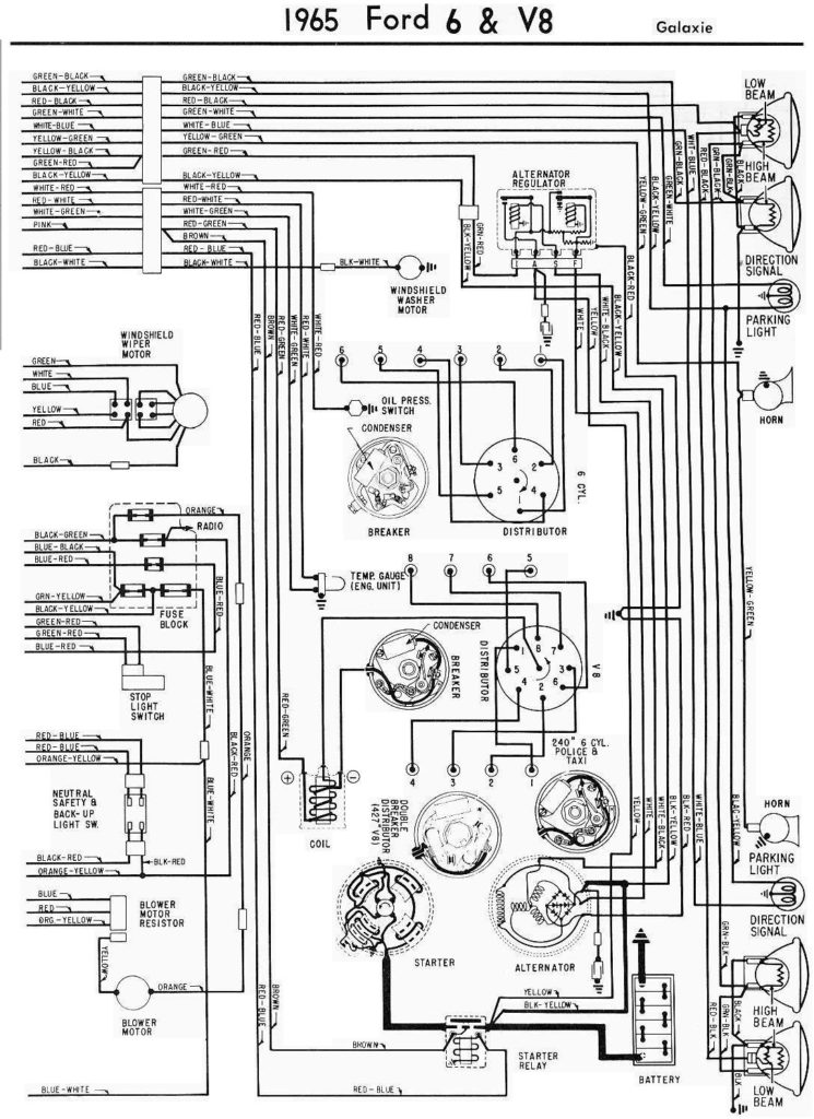
Understanding the terminology is the initial step in finding out what kind of ignition coil you own. An ignition wiring diagram will show a variety of connections and terminals, including two primary and two secondaries. The coils have a specific operating voltage, and the first step to determine which one you’re using is to test the voltage of S1 the main terminal. S1 should be checked for resistance to determine if the coil is type A, B or C.
The chassis’ negative should be connected to connect the coil’s low-tension side. It is also the ground for an ignition wiring diagram. The high-tension side supplies positive direct to the sparkplugs. The body of the coil has to connect to the chassis to suppress the effect but is not electrically essential. The wiring diagram for the ignition will show you how to connect the two terminals of the positive and negative coils. In some cases, a scan at the local auto parts store will be able to diagnose the malfunctioning ignition coils.
The black-and-white-striped wire from the harness goes to the negative terminal. The other white wire has a black trace on it and it goes to the positive terminal. The black wire connects to the contact breaker. If you’re unsure of the connection between both, you can use the clip of a paperclip to remove them from the plug housing. You should also check to ensure that the terminals aren’t bent.
Accessory terminals
Ignition wiring diagrams show the various wires utilized to power the vehicle’s various parts. In general, there are four different color-coded terminals for each component. To identify accessories, red is the starter solenoid’s color, yellow is for battery and blue for accessory. The “IGN” terminal lets you start the car, control the wipers, and any other functions. The diagram below shows how to connect both the ACC terminal and ST terminals to other components.
The terminal BAT connects the battery to the charger. Without the battery, the electrical system does not get started. A dead battery can cause the switch to not turn on. It is possible to refer to your wiring diagram if uncertain about where the car’s batteries are located. The accessory terminals in your car connect to the ignition switch and the battery. The BAT terminal is connected with the battery.
Some ignition switches offer an additional “accessory position” that lets users modify their outputs independent of the ignition. Customers may want to use the auxiliary output in addition to the ignition. The auxiliary output is utilized by wiring the connector with the same color as your ignition and attaching it to the ACC terminal of the switch. This is a great convenience feature, but there is one differentiator. Many ignition switches can be set to have an ACC location when the car has been moved into the ACC position. They’ll also be in START mode after the vehicle has been moved into the IGN position.
Gallery of 1967 Ford Galaxie Ignition Switch Wiring Diagram
Gallery of 1967 Ford Galaxie Ignition Switch Wiring Diagram


