Accuspark Electronic Ignition Wiring Diagram – We will first examine the various types of terminals that are found in the ignition switch. They include terminals for Coil, Ignition Switch, and Accessory. Once we know the terminals used and which ones are not, we can recognize the various parts of the Accuspark Electronic Ignition Wiring Diagram. We’ll also be discussing the function of the Ignition switch and Coil. After that we will move on to the Accessory Terminals.
The ignition switch’s terminals
The ignition switch is comprised of three switches that supply the battery’s current to different destinations. The first switch provides power to the choke whenever pushed, and the second is the position of the ignition switch’s ON/OFF. Different manufacturers have various color codes for the various conductors. This is discussed in another article. OMC uses this method. A connector can be added to the ignition switch to add an electronic Tachometer.
While many ignition switch terminals could not be authentic, the numbering of the terminals may not match the diagram. Check the electrical continuity first to make sure they’re properly connected to the ignition switch. This can be done with a simple multimeter. After you’re happy with the integrity of the wires, then you’ll be able to install the new connector. The wiring loom used for an ignition switch that is supplied by the factory will be different from the one you have in your vehicle.
The first step is to understand the distinctions between the ACC and the auxiliary outputs. The ACC, IGN and START terminals are your default connections to the ignition switch. They are also the primary connections to your radio and stereo. The ignition switch turns the car’s engine ON and OFF. On older cars the terminals of the ignition switch are marked with the letters “ACC” as well as “ST” (for the individual magnet wires).
Terminals for coil
Understanding the terminology that is used is the first step towards finding out the right type of ignition coil. In a basic ignition wiring diagram you’ll see a number of different connections and terminals, which include two primary and two secondary. The voltage that operates on each coil is different. Therefore, it is essential to first check the voltage at the S1 (primary terminal). S1 should be examined for resistance to identify if the coil belongs to Type A, B, or C.
The coil’s low-tension side must be connected with the chassis’ positive. This is also the ground on the wiring diagram for ignition. The high-tension side supplies positive direct to the sparkplugs. It is essential for suppression purposes that the metallic body of the coil is connected to its chassis, however, it is not necessary. The wiring diagram of the ignition will explain how to connect the two terminals of the positive or negative coils. Sometimes, an inspection at an auto part store can diagnose a malfunctioning ignition wire.
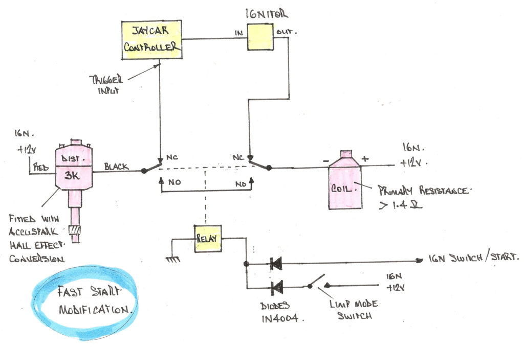
The black-and-white-striped wire from the harness goes to the negative terminal. The terminal that is negative is served by the black trace that’s connected to the white wire. The black wire connects with the contact breaker. If you’re not certain about the connections between the twowires, use the clip of a paperclip to remove them from the plug housing. You should also check to make sure that the connections aren’t bent.
Accessory terminals
Diagrams of ignition wiring show the wiring used in the vehicle’s power supply. There are typically four colors of terminals connected to each part. The red color is for accessories, yellow is the battery and green is the starter solenoid. The “IGN” terminal is used to start the car, operate the wipers and other functions. The diagram illustrates how to connect ACC or ST terminals, and other.
The terminal BAT holds the battery. The electrical system will not start when the battery isn’t connected. Additionally, the switch won’t start. You can view your wiring diagram to determine where the batteries of your car are situated. The accessory terminals of your car are connected to the battery as well as the ignition button. The BAT Terminal is connected to the Battery.
Certain ignition switches come with an “accessory” setting that permits users to control their outputs without having to use the ignition. Sometimes, customers want to use an auxiliary output that is separate from the ignition. You can use the additional output by connecting it to an ACC terminal on your switch using the same colors. This is a great convenience feature however, there’s one difference. Most ignition switches are configured to operate in the ACC position when the vehicle is in the ACC position, whereas they’re set to the START position when the vehicle is in the IGN position.
Gallery of Accuspark Electronic Ignition Wiring Diagram
Gallery of Accuspark Electronic Ignition Wiring Diagram


