Aftermarket Ignition Switch Wiring Diagram – Let’s start by looking at different types of terminals on the ignition switch. These are the terminals for the Ignition, Coil, or Accessory. Once we have identified the purpose of these terminals then we can be able to identify the various parts of the ignition wiring. We’ll also discuss the functions of both the Ignition Switch and Coil. The next step is to focus to the accessory terminals.
Terminals for the ignition switch
Three switches are found on the ignition switch. Each of the three switches transmits the battery’s current to several different locations. The first is used to drive the choke through pushing it, while the second is for the ON/OFF position. Different manufacturers utilize their own color-coding method for different conductors which is explained in a different article. OMC utilizes this method. A tachometer adapter is installed on the ignition switch that allows the addition of an Tachometer.
While most ignition switch terminals are not original, the numbers for each one may not be in line with the diagram. Before plugging in the ignition switch, be sure to test the continuity. This can be done with a cheap multimeter. After you’re satisfied with the integrity of the wires, you can connect the new connector. If your vehicle has an original factory-supplied ignition switch (or a wiring loom), the wiring loom will differ from the one in your vehicle.
Knowing how the ACC outputs are connected to the auxiliary outputs in your car is vital. The ACC terminals as well as the IGN terminals function as the primary connections to the ignition switch. The START and IGN connections are the primary connections for stereo and radio. The ignition switch is responsible for turning the car’s engine on and off. Older vehicles are identified with the alphabets “ACC”, “ST”, (for individual magneto cables) on their ignition switch’s terminals.
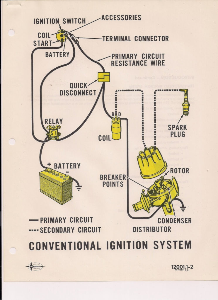
Terminals for coil
Understanding the terms used is the first step towards determining what kind of ignition coil you need. In a typical ignition wiring diagram there are various connections and terminals, such as two primary and two secondary. It is essential to identify the type of coil you have by testing the voltage on the primary terminal, S1. S1 must also be subjected to resistance testing to determine if it is an A or B coil.
The chassis’ negative needs to be connected to the low-tension side. This is what is known as the ground for the wiring for ignition. The high-tension supply provides positively directly to spark plugs. The aluminum body of the coil needs to be linked to the chassis for suppression however it’s not electrically required. The ignition wiring diagram will also reveal how to connect the negative and positive coil’s terminals. Sometimes, a check at an auto part store can detect a defective ignition wire.
The black-and-white-striped wire from the harness goes to the negative terminal. Positive terminal receives the second white wire, which includes a black trace. The black wire is connected to the contactbreaker. If you’re unsure of the connections between the twowires, use a paper clip to remove them from the housing of the plug. You should also check to ensure that the terminals are not bent.
Accessory terminals
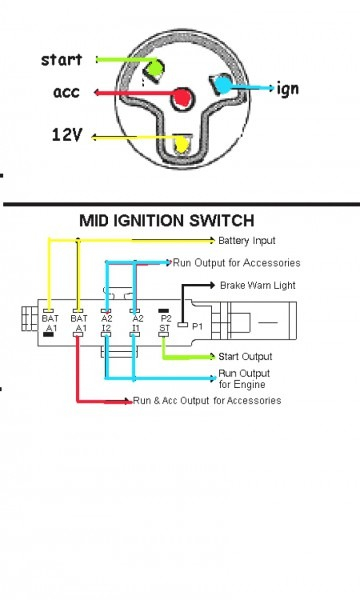
Ignition wiring diagrams depict the various wires utilized for powering the various components. Typically there are four colors-coded terminals that are used for each component. For accessories, red is for starter solenoid, yellow is for battery, and blue for accessory. The “IGN terminal is used to start the vehicle, controlling the wipers, and for other functions. The diagram illustrates how to connect ACC or ST terminals, and other.
The terminal known as BAT is where the battery is connected. The battery is necessary for the electrical system to start. Furthermore, the switch doesn’t turn on. You can view your wiring diagram to figure out where the batteries of your car are located. The ignition switch is connected to the car’s battery. The BAT connector is connected to your battery.
Some ignition switches offer the option of an “accessory position” which allows users to adjust their outputs independently of the ignition. Some customers prefer to make use of an additional output that is independent of the ignition. The auxiliary output is used to connect the connector with the same colors as your ignition and connecting it to the ACC terminal of the switch. Although this is a fantastic feature, there’s one thing you need to know. Most ignition switches are set to have an ACC position when the car is in the ACC position, while they’re in the START position when the vehicle is in the IGN position.
Gallery of Aftermarket Ignition Switch Wiring Diagram
Gallery of Aftermarket Ignition Switch Wiring Diagram


