American Autowire Ignition Switch Wiring Diagram – Let’s begin by examining the different types and functions of the terminals found on the ignition switches. These are the terminals used that are used for Coil, Ignition Switch, and Accessory. After we’ve identified the terminals used and which ones are not, we can recognize the various parts of the American Autowire Ignition Switch Wiring Diagram. We’ll also go over the functions of the Ignition switch and Coil. Next, we’ll discuss the functions of the Ignition switch as well as Coil.
The ignition switch’s terminals
Three switches are found on an ignition switch. Each of these three switches feeds the battery’s voltage to a variety of places. The first switch supplies power to the choke whenever it is pushed. The third is the position of the ignition switch’s ON/OFF. Different manufacturers have various color codes for the various conductors. This is discussed in another article. OMC follows the same system. Connectors can be attached to the ignition switch in order to connect a digital tachometer.
Even though some ignition switch terminals do not come in original form however, the numbers may not match the diagram. It is important to first verify the integrity of the wires to determine if they’re plugged into the ignition switch in the correct way. This can be done using a cheap multimeter. Once you are satisfied with the continuity of the wires, you can install the new connector. The wiring loom for an ignition switch that is factory-supplied will be different than the one that you have in your car.
It is essential to know how the ACC outputs and the auxiliary outputs function to join them. The ACC and IGN terminals are the default connections for your ignition switch, and the START and IGN terminals are the primary connections for radio and stereo. The ignition switch is the one that controls the engine of your car. Older cars are equipped with ignition switch terminals labeled “ACC” or “ST” (for individual magnetowires).
Terminals for coil
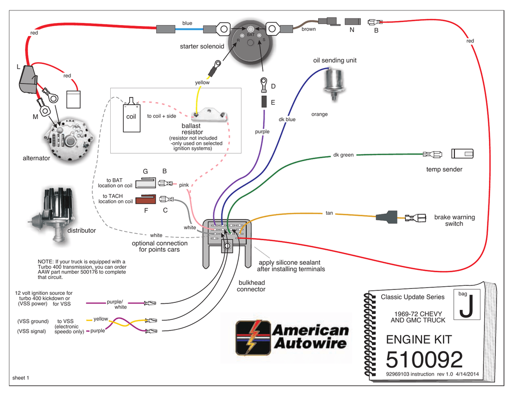
The first step in determining the kind of ignition coil is to know the terms used. The basic ignition wiring diagram depicts various connections and terminals. There are two primary and secondary connections. The voltage that operates on every coil is different. Therefore, it is essential to first check the voltage at the S1 (primary terminal). S1 must also be inspected for resistance to determine whether it’s a Type B, B, or A coil.
The coil’s low-tension side must be connected to the chassis positive. This is also the ground in an ignition wiring diagram. The high tension side supplies positively directly to the spark plugs. It is necessary for suppression purposes that the metallic body of the coil is connected to its chassis, but not essential. There are also connections of the positive and negative coil’s terminals on an ignition wiring diagram. In some instances, you’ll find that the ignition coil is damaged and is identified by scans at an auto parts store.
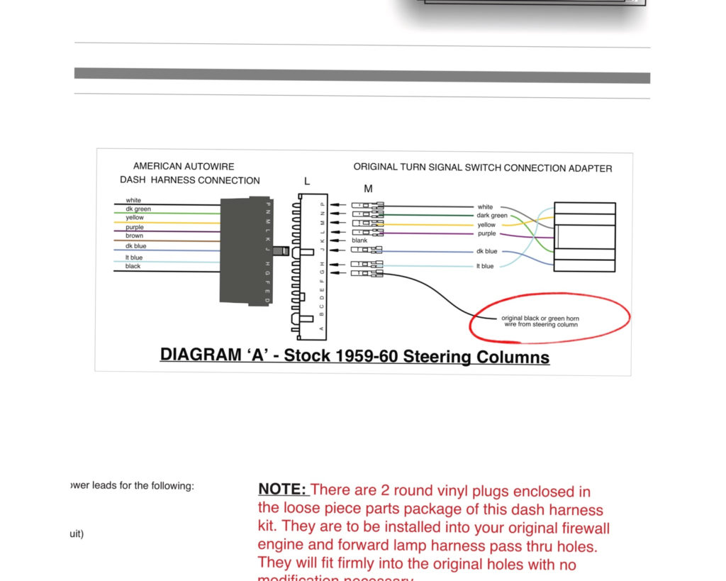
The black-and-white-striped wire from the harness goes to the negative terminal. The positive terminal receives the white wire with an trace in black. The black wire is connected to the contact breaker. To confirm the connections, use a paperclip or a pencil to remove them from the plug housing. Be sure that the terminals aren’t bent.
Accessory Terminals
The wiring diagrams of the ignition illustrate the various wires that are used to power various components of the vehicle. Each part has four distinct color-coded connections. The red color is used for accessories and yellow is for the battery, while green is the solenoid for starters. The “IGN terminal” is used to provide power to the wipers and other operating functions. The following diagram shows how to connect the ACC terminal and ST terminals to various components.
The terminal BAT is the connector for the battery. Without the battery, the electrical system does not begin. Also, the switch won’t turn on without the battery. The wiring diagram will inform you the location of your car’s battery. The accessory terminals in your car are connected with the battery and ignition button. The BAT terminal is connected to the battery.
Some ignition switches come with an independent “accessory” position, where users can control their outputs without using the ignition. Some customers may prefer to utilize the auxiliary output in addition to the ignition. It is possible to use the additional input by connecting it to the ACC terminal. While this is a convenient option, there’s an important difference. Most ignition switches are designed to show an ACC status when the car is at the ACC or START positions.
Gallery of American Autowire Ignition Switch Wiring Diagram
Gallery of American Autowire Ignition Switch Wiring Diagram


