Ba Falcon Ignition Barrel Wiring Diagram – The first step is to examine the different types of terminals on the ignition switch. They include terminals that are used for Coil, Ignition Switch, and Accessory. After we’ve established the purpose of these terminals are for, we will proceed to discover the various components of the Ba Falcon Ignition Barrel Wiring Diagram. We’ll also discuss the functions of both the Ignition Switch and the Coil. Then, we’ll turn our attention to the Accessory terminals.
Terminals of ignition switch
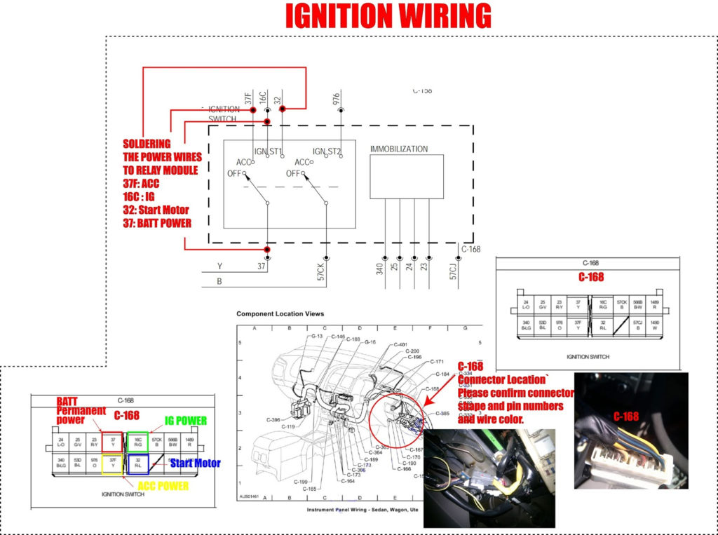
There are three different switches in the ignition switch, and they feed the battery’s voltage to various destinations. The first switch supplies power to the choke whenever it is pushed. The third is the switch that controls the ignition’s ON/OFF positions. Different manufacturers have different color-coding systems to identify different conductors. We will cover this in a separate article. OMC follows this system. The connector allows for the attachment of a speedometer the ignition switch.
While many ignition switch terminals do not come in original form however, the numbers may not match that of the diagram. To make sure that your wires are correctly connected to the ignition switch, it is recommended to check their continuity. A multimeter that is inexpensive can aid in this. When you are satisfied with the continuity of the wires, install the new connector. The wiring loom in an ignition system switch that is supplied by the manufacturer differs.
It is essential to know the way that ACC outputs and auxiliary outputs work in order to connect them. The ACC terminals and IGN terminals are the primary connections to the ignition switch. The START and IGN connections are the most important connections for radio and stereo. The ignition switch switches the engine of your car ON and off. The terminals of older vehicles’ ignition switches are labeled by “ACC” as well as ST (for specific magneto wires).
Terminals for Coil
To determine the type of ignition coil, the first step is to learn the definition of. The basic ignition wiring diagram illustrates a variety of connections and terminals. There are two primary and one secondary. Each coil comes with its own operating voltage. To determine which type of coil you own, the first step is to test the voltage at S1, the primary terminal. S1 must also go through resistance tests to determine if it are an A or B coil.
The low-tension coil side must be connected at the chassis’s plus. It is also the ground for an ignition wiring diagram. The high-tension side supplies positive direct to the spark plugs. To prevent noise the coil’s body metal must be connected to the chassis. This is not necessary for electrical use. The ignition wiring diagram will also show how to connect the positive coil terminals. Sometimes, a check at an auto part store can identify a problem with the ignition wire.
The black-and-white-striped wire from the harness goes to the negative terminal. The other white wire has a black trace, and it connects to the positive terminal. The black wire goes to the contact breaker. To verify the connections, make use of a paperclip or pencil to lift them out of the plug housing. You should also check to ensure that the terminals aren’t bent.
Accessory terminals
Diagrams of ignition wiring show the various wires used to power the car’s various parts. There are generally four color-coded terminals to each component. Red is for accessories, yellow is for the battery, and green is the solenoid for starters. The “IGN” terminal can be used to start the car, operate the wipers, as well as other features. The diagram below illustrates how to connect the ACC terminal and ST terminals to various components.
The terminal called BAT is where the battery is connected. The electrical system cannot begin without the battery. In addition, the switch will not start. A wiring diagram can tell you the location of the battery of your car. The accessory terminals of your vehicle are connected to the battery as well as the ignition switch. The BAT connector connects to your battery.
Certain ignition switches have an additional “accessory” position, where users can manage their outputs with no ignition. Sometimes, customers would like an auxiliary output that can be used separately from the ignition. The auxiliary output can be used by wiring the connector in the same color as your ignition and connecting it to the ACC terminal of the switch. This feature is convenient however, it does have one significant distinction. Some ignition switches are configured to be in an ACC position once the car is in the ACC position. They also will be in the START position when the vehicle has entered the IGN position.
Gallery of Ba Falcon Ignition Barrel Wiring Diagram
Gallery of Ba Falcon Ignition Barrel Wiring Diagram


