Basic 12 Volt Ignition Wiring Diagram – First, we will examine the different types of terminals on the ignition switch. The terminals are the Ignition switch as well as the Coil and the Accessory. When we have a clear understanding of the purpose of each kind of terminal, we can then identify the various components of the ignition wiring. In addition, we will discuss the functions of both the Ignition Switch and Coil. After that, we will concentrate on the accessories terminals.
Terminals for ignition switch
There are three different switches on an ignition switch, which transmit the battery’s current voltage to various places. The first one is used to drive the choke through pushing it, while the second is for the ON/OFF setting. Different manufacturers have different colors-coding systems to match the conductors. OMC follows this method. The adapter is attached to the ignition switch to allow the installation of a tachometer.
Even though most ignition switch terminals do not have an original number, they may have a different one. It is important to first verify the integrity of the wires to ensure that they are plugged into the correct ignition switch. This can be done with a cheap multimeter. Once you’re satisfied about the integrity of your wires, you’ll be able install the new connector. The wiring loom of an ignition switch that is factory-supplied will be different than the one that you have in your vehicle.
To connect the ACC outputs to the auxiliary outputs of your car, you need to understand how these two connections work. The ACC terminals as well as the IGN terminals function as the standard connections for the ignition switch. The START and IGN connections are the primary connections for stereo and radio. The ignition switch is responsible to turn the car’s engines on and off. In older vehicles the terminals of the ignition switch are marked with the initials “ACC” as well as “ST” (for the individual magnet wires).
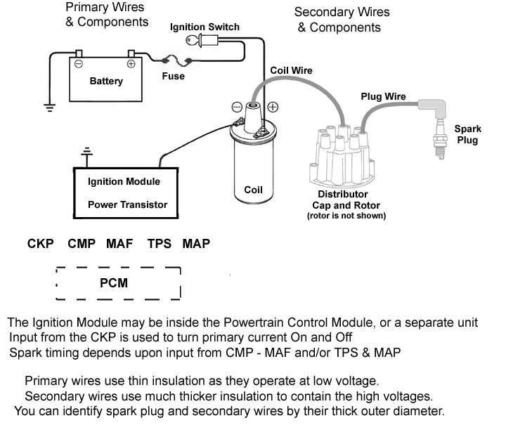
Terminals for coil
The terms used to define the type and model of the ignition coil is the first thing. You’ll see a number of connections and terminals on a basic ignition wiring schematic, including two primary, as well as two secondary. The voltage that operates on each coil is different. This is why it is important to first test the voltage at S1 (primary terminal). S1 should also be checked for resistance to determine whether it’s a Type B, B or an A coil.
The chassis’ negative must be connected to the side of low-tension. This is what’s called the ground in the ignition wiring diagram. The high tension part supplies positive power directly to the spark plugs. It is necessary to suppress the body of the coil’s metal be connected to its chassis, but not essential. The ignition wiring diagram will also indicate the connection of the positive coil’s terminals. Sometimes, a malfunctioning ignition coil can be identified with a scan in an auto parts shop.
The black-and-white-striped wire from the harness goes to the negative terminal. The other white wire has a black trace on it, and it connects to the positive terminal. The black wire is connected to the contactbreaker. It is possible to remove the black wire from the housing of the plug by using a paperclip if you are unsure about the connection. Be sure the terminals don’t bend.
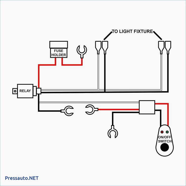
Accessory Terminals
Ignition wiring diagrams show the various wires utilized to power the vehicle’s various parts. There are usually four different color-coded terminals to each component. The red symbol represents accessories, yellow represents the battery and green is for the starter solenoid. The “IGN” terminal is used to start the car, operating the wipers, and for other functions. The following diagram shows how to connect both the ACC terminal as well as the ST terminals to other components.
The battery is connected to the terminal called BAT. The electrical system will not start in the event that the battery isn’t connected. The switch won’t turn off if the battery isn’t there. To locate your car’s battery, check your wiring diagram. The ignition switch is connected to the battery of your car. The BAT terminal is connected to the battery.
Some ignition switches come with the option of an “accessory position” that lets users adjust their outputs independently of the ignition. Some customers want an auxiliary output that can be operated independently of the ignition. Make use of the auxiliary output by connecting the connector to the ACC terminal on your switch using the same colors. This is a convenient feature however it does have one major distinction. Most ignition switches are configured to have an ACC status when the car’s at the ACC or START position.
Gallery of Basic 12 Volt Ignition Wiring Diagram
Gallery of Basic 12 Volt Ignition Wiring Diagram


