Bayliner Ignition Switch Wiring Diagram – Let’s begin by looking at the various kinds of terminals that are found on the ignition switch. These include the terminals for the Ignition switch, Coil, and Accessory. Once we have identified what these terminals are then we can determine the various components in the ignition wiring. We’ll also discuss the functions of the Ignition switch and Coil. We will then discuss the roles of the Ignition switch as well as Coil.
The terminals of the ignition switch
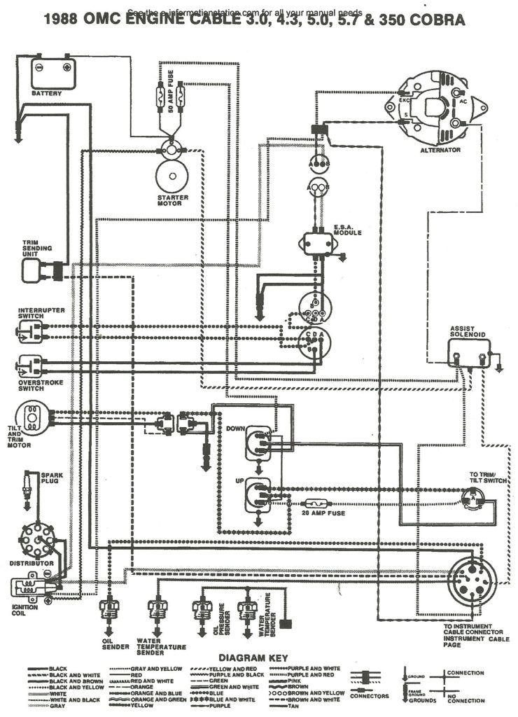
The ignition switch is comprised of three separate switches that feed the battery’s power to various locations. The choke is powered by the first switch. The third switch regulates the ON/OFF function of the ignition switch. Different manufacturers have distinct colour-coding systems that correspond to the conductors. OMC uses this system. An additional connector is included inside the ignition switch for attaching an Tachometer.
While most ignition switch terminals can be duplicated, the numbers might not match the diagram. You should first check the integrity of the wires to ensure that they are plugged into the ignition switch in the correct way. A multimeter is a good tool to test the continuity. Once you’ve verified that the wires are in good condition, you can then connect the connector. The wiring loom of an ignition system switch that is supplied by the manufacturer differs.
To connect the ACC outputs to the auxiliary outputs on your car, you need to first understand the way these two connections function. The ACC, IGN and START terminals are the default connections to the ignition switch. They are also the primary connections to your radio and stereo. The ignition switch is responsible for turning the car’s engine on and off. The terminals of older vehicles ignition switches are marked by “ACC” and ST (for specific magneto wires).
Terminals for coil
Understanding the terminology is the initial step towards determining which type of ignition coil you have. In a basic ignition wiring diagram, you will see a number of different connections and terminals, such as two primary and two secondary. Each coil has a specific operating voltage. To determine what kind of coil you’ve got, the first step is to test the voltage at S1, which is the primary terminal. S1 must be tested for resistance in order to determine if the coil belongs to Type A, B, and/or C.
The low-tension end of the coil should be connected to the chassis’ negative. This is what’s called the ground in the diagram of the ignition wiring. The high-tension side is a positive connection to the sparkplugs. The aluminum body of the coil has to be connected to the chassis for suppression but isn’t required. The diagram of the ignition wiring will also indicate the connection of the positive coil’s terminals. Sometimes, a check at an auto parts store could detect a defective ignition wire.
The black-and-white-striped wire from the harness goes to the negative terminal. The terminal for the negative is served by the black trace that’s connected to the white wire. The black wire is connected to the contactbreaker. If you’re not sure about the connections of both, you can use a paper clip to remove them from the plug housing. Check that you don’t bend the connectors.
Accessory terminals
The ignition wiring diagrams show the various wires that are used to power the various components. There are typically four terminals with color codes that are connected to the component. The red color is for accessories, yellow the battery, and green for the starter solenoid. The “IGN terminal is used to start the vehicle, controlling the wipers and other functions. This diagram shows how you can connect ACC and ST terminals to the other components.
The terminal referred to as BAT is the place where the battery is. The electrical system won’t start in the event that the battery isn’t connected. In addition the switch isn’t turned on. If you’re not sure of where your car’s battery is situated, look at your wiring diagram to figure out where it is. The ignition switch is connected to the car’s battery. The BAT Terminal is connected to the battery.
Certain ignition switches have an accessory position. It allows users to access their outputs from another location without the ignition. Sometimes, customers would like the output of the auxiliary to be used separately from the ignition. You can use the secondary input by connecting it to the ACC terminal. While this is an excellent feature, there’s one thing to be aware of. A majority of ignition switches feature the ACC position when your car is in the ACC mode and a START mode when it is in IGN.
Gallery of Bayliner Ignition Switch Wiring Diagram
Gallery of Bayliner Ignition Switch Wiring Diagram


