Car Ignition Wiring Diagram – We will first look at the various types and functions of the terminals on the ignition switches. These are the terminals for the Ignition, Coil, or Accessory. Once we’ve determined the function of the terminals we can recognize the various parts of the ignition wiring. In addition, we will discuss the function of the Ignition switch and Coil. After that we will proceed to the Accessory Terminals.
Terminals for ignition switches
An ignition switch is composed of three different switches. They are responsible for feeding the battery’s power to various locations. The first switch powers the choke. The second switch controls the ON/OFF switch of the ignition switch. Different manufacturers have different color-coding schemes for different conductors. This will be covered in a different article. OMC uses this method. This connector allows the attachment of a speedometer to the ignition switch.
Although the majority of ignition switch terminals do not have an original number, they may have a different one. To make sure that your wires are properly plugged in to the switch, it is recommended to check their continuity. A multimeter that is inexpensive can assist you in this. Once you are happy with the continuity of the wires it is time to connect the new connector. The wiring loom used in the ignition system switch supplied by the manufacturer is different.
Understanding how the ACC outputs are connected to the auxiliary outputs in your vehicle is crucial. The ACC and IGN terminals are the default connections for your ignition switch. the START and IGN terminals are the primary connections to the stereo and radio. The ignition switch is the engine’s switch to turn off or on. The terminals on older cars’ ignition switches are labeled with “ACC” as well as ST (for individual magneto wires).
Terminals for coil
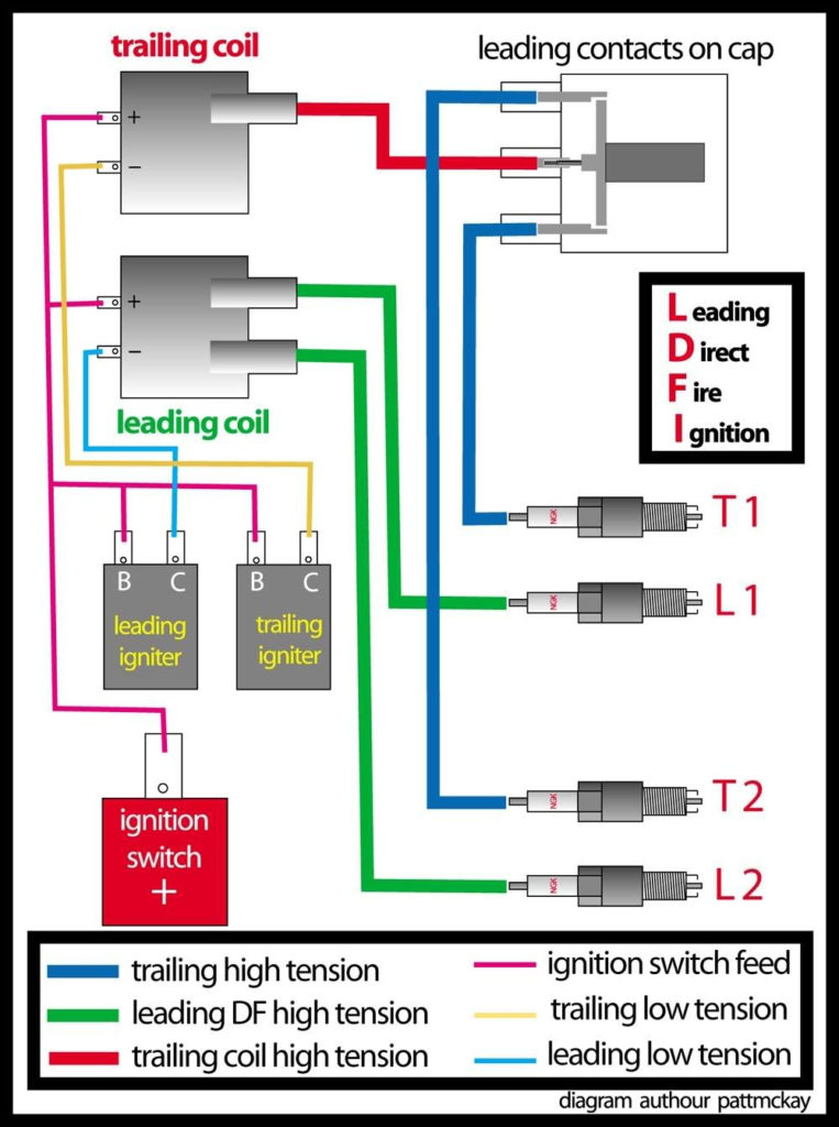
The first step to determine the kind of ignition coil is to comprehend the terms employed. You will see several connections and terminals on an ignition wiring schematic that include two primary as well as two secondary. It is essential to identify the type of coil you are using by testing the voltage on the primary terminal, S1. It is also recommended to check S1 for resistance in order to identify if it’s an A or B coil.
The low-tension end of the coil must be connected to the chassis the negative. This is the ground on the diagram of ignition wiring. The high-tension component supplies positive direct to the spark plugs. The aluminum body of the coil has to be connected to the chassis to prevent it from being smothered however it’s not electrically required. The ignition wiring diagram will also show the connection of the positive coil’s terminals. Sometimes, a malfunctioning ignition coil can be identified by a scan done at an auto parts shop.
The black-and-white-striped wire from the harness goes to the negative terminal. The white wire is black and goes to the negative terminal. The black wire is connected to the contact breaker. To verify the connections between the two wires, use a paperclip and lift them off the housing. It is also important to make sure the terminals do not bend.
Accessory terminals
Ignition wiring diagrams show the different wires that are used to power the car’s various components. There are usually four colors-coded terminus of each part. The red color represents accessories, yellow represents the battery and green is for the solenoid for starters. The “IGN” terminal allows you to start your car, operate the wipers or other features that operate. The diagram demonstrates how to connect the ACC and ST terminals to the rest of the components.
The terminal BAT connects the battery to the charger. The battery is essential for the electrical system to begin. A dead battery can cause the switch to not turn on. If you’re not sure of where your car’s battery is located, you can review your wiring diagram to figure out where it is. The ignition switch is connected to the car’s battery. The BAT terminal is connected with the battery.
Certain ignition switches have an accessory position where users can modify their outputs and control them without the need to use the ignition. Sometimes, customers want to utilize an additional output that is independent of the ignition. You can use the additional output by connecting the connector to an ACC terminal on your switch using the same colors. This is an excellent feature, however there’s one important difference. Most ignition switches are configured to display an ACC status when the car is in either the ACC or START positions.
Gallery of Car Ignition Wiring Diagram
Gallery of Car Ignition Wiring Diagram


