Cdi Ignition Coil Wiring Diagram – First, we will take a look at the different kinds of terminals that are used on the ignition switch. These are terminals for the Ignition, Coil, or Accessory. Once we have identified the terminals that are utilized then we can identify the different components of the Cdi Ignition Coil Wiring Diagram. We will also discuss the roles of the Ignition switch and Coil. Then, we will concentrate on the accessory terminals.
Terminals for ignition switches
An ignition switch is made up of three switches. These are responsible for supplying the battery’s power to various destinations. The first switch provides the choke with power, while the second toggles the ON/OFF status of the ignition switch. Different manufacturers employ different color codes for various conductors. This is discussed in a different article. OMC uses the same method. A connector can be added to the ignition switch in order to connect a digital tachometer.
Although the majority of ignition switch terminals are not original, the numbers for each might not be consistent with the diagram. First, check the continuity of each wire to make sure they’re properly plugged into the ignition switches. A simple multimeter will aid in this. After you have verified that the wires are in good condition, you are able to connect the connector. The wiring loom for an ignition switch that’s factory-supplied will be different than the one that you have in your vehicle.
Before connecting the ACC outputs to your car’s auxiliary outputs It is essential to know the fundamentals of these connections. The ACC terminals and IGN terminals serve as the default connections to the ignition switch. The START and IGN connections are the most important connections for stereo and radio. The ignition switch is the one that controls the engine of your car. Older vehicles are identified with the letters “ACC”, “ST”, (for individual magneto cables) at their ignition switch’s terminals.
Terminals for coil
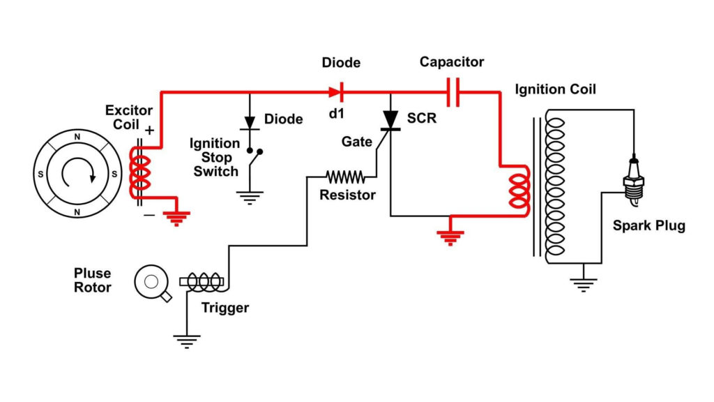
The language used to decide the model and type of an ignition coil is the most important thing. A simple diagram of the wiring will show a variety of connections and terminals, comprising two primary and two secondary. The coils are equipped with a particular operating voltage. The first step to determine which one you’re using is to test the voltage of S1 the primary terminal. S1 must be examined for resistance to determine if the coil belongs to Type A, B, and/or C.
The chassis’ negative needs to be connected to the side of low-tension. This is also the ground in an ignition wiring diagram. The high tension part supplies positively directly to the spark plugs. For suppression purposes the body of the coil is required to be connected to the chassis. However, it is not required to connect electrically. The wiring diagram of the ignition will explain how to connect the terminals of either the positive and negative coils. Sometimes, an inspection at an auto parts shop can diagnose a malfunctioning ignition wire.
The black-and-white-striped wire from the harness goes to the negative terminal. The white wire is black-colored and connects to the terminal opposite. The contact breaker is linked to the black wire. If you’re not certain about the connection between both, you can use a paper clip to remove them from the housing of the plug. It’s also crucial to make sure that the terminals don’t bend.
Accessory terminals
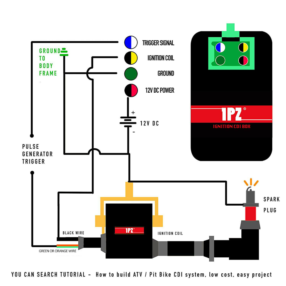
Diagrams of the ignition wiring show the wires that provide power to various components of the vehicle. Each part has four distinct connections that are color coded. For accessories, red stands for starter solenoid, yellow for battery, and blue is for accessories. The “IGN” terminal allows you to start your car, operate the wipers, or any other operation features. The diagram shows how to connect ACC or ST terminals as well as the rest.
The battery is attached to the terminal called BAT. The electrical system will not start if the battery isn’t connected. A dead battery could cause the switch to not come on. You can view your wiring diagram to determine where the batteries of your car are placed. The accessory terminals of your car are connected with the battery and the ignition button. The BAT terminal is connected to the battery.
Certain ignition switches have a separate “accessory” position, where users can control their outputs with no ignition. In some cases, users may want to use the auxiliary output separately from the ignition. You can use the additional input by connecting it to the ACC terminal. Although this is a fantastic feature, there’s one thing to be aware of. The majority of ignition switches are configured to have an ACC status when the vehicle is at either the ACC or START positions.
Gallery of Cdi Ignition Coil Wiring Diagram
Gallery of Cdi Ignition Coil Wiring Diagram


