Chevrolet Ignition Wiring Diagram – Let’s first examine the different kinds and functions of terminals on the ignition switches. These terminals include the Ignition switch and Coil as well as the Accessory. After we’ve identified the purpose of these terminals, it is possible to recognize the various parts of the ignition wiring. We will also discuss what functions are available for the Ignition switch as well as the Coil. The next step is to focus on the accessory terminals.
The ignition switch’s terminals
There are three separate switches on an ignition switch that feed the battery’s voltage to various locations. The choke is powered by the first switch. The second switch is responsible for the ON/OFF switch of the ignition switch. Different manufacturers use different color-coding methods for different conductors. We’ll discuss this in another article. OMC uses the same method. The ignition switch is also equipped with an adapter for the addition of a tachometer.
While the majority of the ignition switch terminals may not be original, the numbering for each one may not be in line with the diagram. Examine the integrity of the wires first to ensure that they are correctly plugged in the ignition switch. A multimeter is a great tool to test the continuity. Once you are satisfied that all wires are running in good harmony then you can connect the new connector. If your car is equipped with an original factory-supplied ignition switch (or an electrical loom) the wiring loom may differ from that in the car.
Understanding how ACC outputs connect to the auxiliary outputs in your car is essential. The ACC terminals as well as the IGN terminals are the default connections to the ignition switch. The START and IGN connections are the main connections for stereo and radio. The ignition switch turns the car’s engine ON and off. The terminals of older vehicles’ ignition switches are labeled by “ACC” and ST (for individual magneto wires).
Terminals for coil
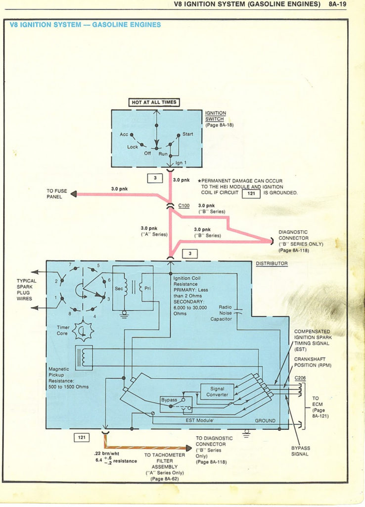
Understanding the terminology used is the first step to finding out the right kind of ignition coil you need. The fundamental diagram of ignition wiring illustrates a variety of connections and terminals. There are two primary and secondary connections. It is essential to identify the type of coil that you own by examining the voltage on the primary terminal, S1. S1 must be checked for resistance to determine if the coil is Type A, B, and/or C.
The low-tension side of the coil should be connected to the chassis the negative. This is the ground of the wiring for ignition. The high-tension side supplies the spark plugs with positive. To prevent noise, the coil’s metal body is required to be connected to the chassis. But, it’s not required to connect electrically. The diagram of the ignition wiring will also indicate how to connect the positive coil terminals. Sometimes, a check at an auto parts shop can diagnose a malfunctioning ignition wire.
The black-and-white-striped wire from the harness goes to the negative terminal. The white wire has a black color and goes to the terminal opposite. The black wire connects to the contact breaker. To check the connections, use a paperclip or a pencil to lift them out from the plug housing. Be sure that the terminals aren’t bent.
Accessory terminals
Ignition wiring diagrams depict the various wires that are used to power different components. There are typically four colored terminals that correspond to each component. To identify accessories, red stands the starter solenoid’s color, yellow is for battery, and blue is for accessories. The “IGN” terminal is used for starting the car, operating the wipers and other functions. The diagram illustrates how you can connect ACC or ST terminals as well as the rest.
The terminal referred to as BAT is the location where the battery is. The electrical system won’t start in the event that the battery isn’t connected. The switch will not turn on if there is no battery present. If you’re not sure of the location of your car’s battery located, you can examine your wiring diagram to figure out how to locate it. The ignition switch is connected to the battery of your car. The BAT Terminal is connected to the Battery.
Some ignition switches come with an accessory position. This lets users connect their outputs to another location without having to turn on the ignition. Customers sometimes want the auxiliary output to be operated independently of the ignition. To allow the auxiliary output to be used, connect the connector with the same color as that of the ignition. Then connect it with the ACC end of the switch. Although this is a useful option, there’s an important difference. Most ignition switches will have an ACC position when the vehicle is in ACC however, they’ll be at the START position if the car is in IGN.
Gallery of Chevrolet Ignition Wiring Diagram
Gallery of Chevrolet Ignition Wiring Diagram


