Club Car Ignition Wiring Diagram – We will first look at the various types and purposes of the terminals that are found on the ignition switches. They include terminals for the Ignition switch, Coil, and Accessory. After we’ve identified the purpose of the terminals we will be able to identify the various parts of the ignition wiring. Then, we will discuss the roles of the Ignition switch and the Coil. We’ll then turn our attention on the accessory terminals.
The terminals of the ignition switch
An ignition switch is composed of three switches. These are responsible for feeding the battery’s power to several locations. The first switch provides the choke with power when it is pushed. The third is the ignition switch’s ON/OFF position. Each manufacturer has its own color-coding system, which we’ll discuss in a subsequent article. OMC utilizes this system. The connector permits the attachment of a speedometer to the ignition switch.
While most ignition switch terminals aren’t authentic, the numbering of each may not match the diagram. Examine the integrity of the wires first to make sure they are correctly plugged in the ignition switch. This can be done using an inexpensive multimeter. After you’re happy with the continuity of the wires install the new connector. The wiring loom of the ignition switch supplied by the factory will be different from the one in your car.
To connect the ACC outputs to the auxiliary outputs on your vehicle, you have to first understand the way these two connections function. The ACC and IGN terminals are the default connections for your ignition switch, and the START and IGN terminals are the main connections to the radio and stereo. The ignition switch controls the car’s engine. Older cars are identified with the letters “ACC”, “ST”, (for individual magneto cables) at their ignition switch’s terminals.
Terminals for coil
The first step to determine the kind of ignition coil is to understand the terms that is used. In a typical ignition wiring diagram you’ll see several different connections and terminals, such as two primary and two secondary. The coils are equipped with a particular operating voltage. The initial method of determining what type you’ve got is to check the voltage at S1, the primary terminal. S1 must also be inspected for resistance to determine whether it’s an A, Type B, or an A coil.
The negative of the chassis must be connected to the side of low-tension. This is also the ground in an ignition wiring diagram. The high-tension part supplies positive direct to the sparkplugs. To prevent noise, the coil’s body metal must be connected with the chassis. This is not necessary to use electricity. The diagram of the ignition wiring will also demonstrate the connections between the negative and positive coil terminals. In certain instances you’ll discover that an ignition coil that is malfunctioning is easily identified with a scan at an auto parts store.
The black-and-white-striped wire from the harness goes to the negative terminal. The terminal for the negative is served by the trace in black that’s joined to the white wire. The black wire connects to the contact breaker. You can check the connections with a paperclip to take the wires out from the housing. It’s also crucial to make sure the terminals don’t bend.
Accessory terminals
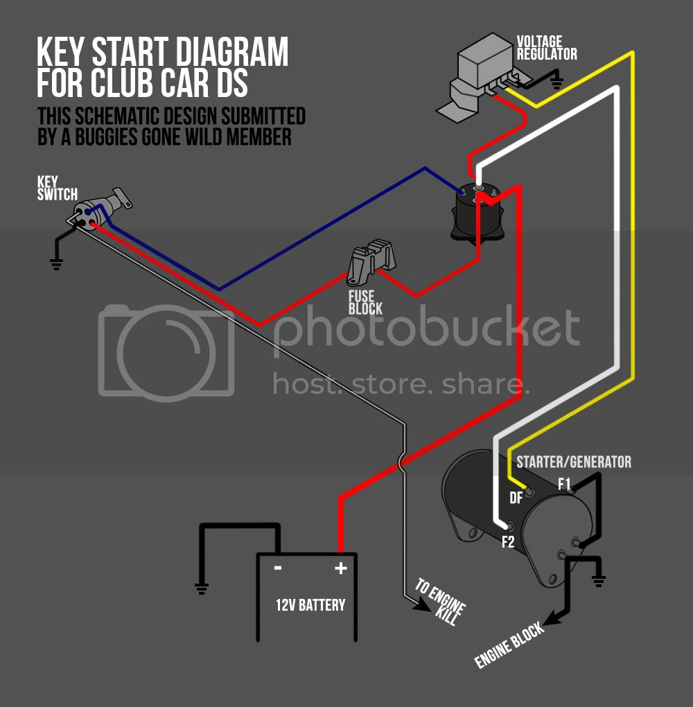
Diagrams of the ignition wiring depict the wires that provide power to various components of the vehicle. There are generally four color-coded terminus for each component. Red stands for accessories, yellow represents the battery, and green for the solenoid for starters. The “IGN” terminal lets you start the car, control the wipers, and any other operation features. The diagram demonstrates how to connect the ACC and ST terminals to the other components.
The terminal BAT is where the battery is. The battery is essential for the electrical system to get started. Additionally, the switch won’t start. You can view your wiring diagram to determine where the batteries of your car are placed. The ignition switch as well as the battery are connected by the accessory terminals. The BAT connector is connected to the battery.
Some ignition switches offer an additional “accessory position” that lets users adjust their outputs independently of the ignition. Customers sometimes want the auxiliary output to be used independently from the ignition. To make use of the auxiliary output, wire the connector with the same colors as ignition, connecting it to the ACC terminal on the switch. This is a convenient feature however it does have one significant differentiator. Most ignition switches will be in an ACC position when the vehicle is in ACC however they’ll be in the START position when the vehicle is IGN.
Gallery of Club Car Ignition Wiring Diagram
Gallery of Club Car Ignition Wiring Diagram


