Craftsman Ignition Switch Wiring Diagram – We will first examine the different types of terminals on the ignition switch. The terminals are the Ignition switch as well as the Coil along with the Accessory. Once we have established the purpose of these terminals are used for, we will proceed to discover the various components of the Craftsman Ignition Switch Wiring Diagram. We will also cover the functions of both the Ignition Switch and the Coil. After that, we’ll turn our attention to Accessory terminals.
The terminals are for ignition switches.
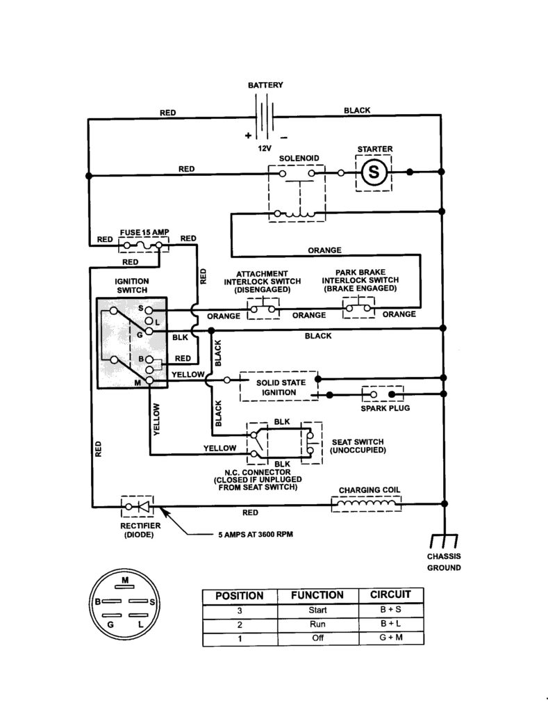
The ignition switch has three switches. They transmit the battery’s voltage to different locations. The ON/OFF state of the switch that controls the ignition is managed by the third switch, which provides power to the choke when it is pushed. Different manufacturers use different color-coding methods for different conductors. We will cover this in another article. OMC utilizes this method. The ignition switch is also equipped with a connector for adding a timer.
While the majority of ignition switch terminals don’t have an original number, they might have a different number. Check the electrical continuity first to make sure they’re connected correctly to the ignition switch. A multimeter is an excellent instrument to verify the continuity. When you’re satisfied that the wires are in good continuity, you can attach the new connector. The wiring loom for an ignition switch that is supplied by the manufacturer will differ from the one you have in your car.
You must first understand the ways in which the ACC outputs and the auxiliary outputs work in order to join them. The ACC terminals as well as the IGN terminals serve as the standard connections for your ignition switch. The START and IGN connections are the main connections for radio and stereo. The ignition switch is responsible for turning the car’s engine to and off. The terminals on older cars ignition switches are marked with “ACC” as well as ST (for specific magneto wires).
Coil terminals
Understanding the terms is the first step to determining which type of ignition coil you have. A basic ignition wiring diagram will reveal a variety of terminals and connections, which include two primary terminals and two secondaries. Each coil operates at a specific voltage. The first step in determining which kind you’re using is to examine the voltage at S1 or the primary terminal. To determine whether it’s an A, C, or B coil you must also check the resistance of S1.
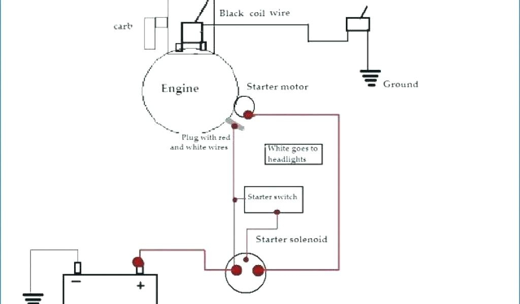
The coil’s low-tension end must be connected with the chassis positively. This is the ground in the wiring diagram for ignition. The high tension part supplies positive power directly to the spark plugs. For suppression purposes the coil’s metal body must be connected with the chassis. It’s not necessary to use electricity. The diagram of the ignition wiring will also indicate how to connect the positive coil terminals. Sometimes, a check at an auto part store can diagnose a malfunctioning ignition wire.
The black-and-white-striped wire from the harness goes to the negative terminal. The positive terminal is connected to the white wire, which has the black trace. The black wire is connected to the contact breaker. You can remove the black wire from the plug housing using a paper clip in case you are uncertain about the connections. Make sure that the terminals do not bend.
Accessory terminals
Ignition wiring diagrams show the various wires utilized to power the vehicle’s various components. There are typically four terminals with color codes that are connected to the respective component. Red is for accessories while yellow is the battery, and green is the starter solenoid. The “IGN” terminal allows you to start the car, control the wipers, and any other functions. The diagram below shows how to connect the ACC terminal as well as the ST terminals to various components.
The terminal BAT is the connection to the battery. The battery is necessary for the electrical system to get started. Additionally, the switch doesn’t turn on. You can refer to your wiring diagram if you’re uncertain about where the car’s batteries are located. The ignition switch is linked to the car’s battery. The BAT Terminal is connected to the battery.
Some ignition switches come with an additional position. This allows users to connect their outputs to another location without the ignition. Sometimes, a customer wants to utilize an auxiliary output that is separate from the ignition. Make use of the additional output by connecting it to an ACC terminal on the switch using the same colors. This is an excellent feature, but there is one important distinction. Many ignition switches can be configured to be in an ACC position once the car is in the ACC position. They’ll also be in START mode once the vehicle is moved into the IGN position.
Gallery of Craftsman Ignition Switch Wiring Diagram
Gallery of Craftsman Ignition Switch Wiring Diagram


