Crane Hi-6 Ignition Box Wiring Diagram – Let’s begin by looking at the different kinds of terminals that are found on the ignition switch. These terminals are used for the Ignition button, Coil and Accessory. Once we understand the function of each terminal, it is possible to determine the components of the ignition wiring. We’ll also go over the roles of the Ignition switch and Coil. Then, we will turn our attention towards the accessories terminals.
Terminals for ignition switches
An ignition switch is comprised of three switches. They feed the voltage of the battery to many different places. The first switch provides power to the choke, while the second toggles the ON/OFF state of the switch. Different manufacturers use different color-coding systems that correspond to the conductors. OMC follows this scheme. A tachometer adapter is installed on the ignition switch that allows the installation of the Tachometer.
Even though some of the ignition switch terminals might not be original, the numbers of each may not be in line with the diagram. Before you plug into the ignition switch, be sure to test the continuity. This can be done with an inexpensive multimeter. After you’re happy with the continuity of the wires, then you’ll be able to connect the new connector. The wiring loom used for the ignition switch factory-supplied will be different than the one in your car.
Before connecting the ACC outputs to your car’s auxiliary outputs it is crucial to understand the basics of these connections. The ACC terminals as well as the IGN terminals serve as the primary connections to the ignition switch. The START and IGN connections are the most important connections for stereo and radio. The ignition switch is the one that controls the engine of your car. The terminals on older cars ignition switches are identified with “ACC” as well as ST (for the individual magneto wires).
Terminals for coil
Understanding the terminology used is the first step in finding out the right kind of ignition coil you need. The basic ignition wiring diagram illustrates a variety of connections and terminals. There are two primary and secondary connections. Each coil has an operating voltage. The first step to determine which kind of coil you have is to check the voltage on S1, or the primary terminal. S1 must be examined for resistance to identify if the coil is type A, B or C.
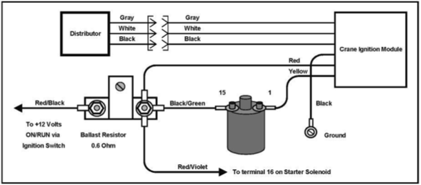
The low-tension coil side must be connected to the chassis’ less. This is the ground in the diagram of the ignition wiring. The high tension side supplies positively directly to the spark plugs. The coil’s aluminum body needs to be connected to the chassis for suppression, but it isn’t electrically required. The ignition wiring diagram will also indicate the connection of the positive coil terminals. In some cases scanning your local auto parts shop can help you identify the malfunctioning ignition coils.
The black-and-white-striped wire from the harness goes to the negative terminal. The white wire also is black with a trace on it, and it goes to the positive terminal. The contact breaker is linked to the black wire. You can remove the black wire from the plug housing using a paper clip If you’re unsure of the connections. Also, ensure that the terminals aren’t bent.
Accessory terminals
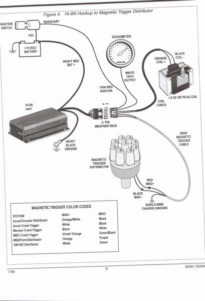
Diagrams of ignition wiring show the different wires that are utilized to power the vehicle’s various parts. There are generally four colors of terminals connected to each part. For accessories, red stands for starter solenoid, yellow is for battery and blue for accessory. The “IGN terminal” is used to provide power to the wipers as well as other operating functions. The diagram illustrates the connection between the ACC- and ST terminals.
The terminal BAT is the connection for the battery. The battery is vital to allow the electrical system to start. Additionally, the switch doesn’t turn on. To find the battery in your car look over your wiring diagram. The accessory terminals in your car are connected to the ignition switch as well as the battery. The BAT Terminal is connected to the battery.
Some ignition switches feature an “accessory” position that permits users to control their outputs without needing to turn on the ignition. Customers may want to utilize the auxiliary output in addition to the ignition. You can use the additional input by connecting the connector to the ACC terminal. Although this is a fantastic option, there’s a thing you should know. Most ignition switches come with an ACC position when the car is in the ACC mode and a START position when you are in IGN.
Gallery of Crane Hi-6 Ignition Box Wiring Diagram
Gallery of Crane Hi-6 Ignition Box Wiring Diagram


