Defender 300tdi Ignition Switch Wiring Diagram – The first step is to take a look at the different types of terminals that are used in the ignition switch. These are terminals for the Ignition, Coil, or Accessory. When we have a clear understanding of the purpose of each kind of terminal, it is possible to identify the various components of the ignition wiring. We’ll also discuss the functions as well as the Coil. After that we will move on to the Accessory Terminals.
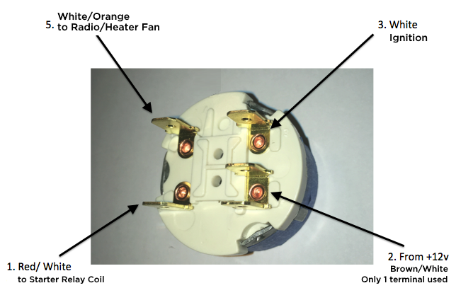
Terminals of ignition switch
Three switches can be found on an ignition switch. Each of these three switches feeds the battery’s voltage to a variety of destinations. The first switch provides the choke with power, while the second switch controls the ON/OFF state of the switch. Each manufacturer has their individual color-coding system that we will discuss in another article. OMC uses this system. The ignition switch also includes an adapter for the addition of the Tachometer.
Although the majority of ignition switch terminals may not be original, the numbers for each one may not be in line with the diagram. Verify the electrical continuity first to ensure that they’re properly connected to the ignition switch. A cheap multimeter can aid in this. When you’re happy with the continuity, you can place the new connector. The wiring loom used for an ignition switch that’s factory-supplied will be different than the one that you have in your car.
Knowing how the ACC outputs are connected to the auxiliary outputs of your vehicle is crucial. The ACC and IGN connectors are the default connections for the ignition switch. The START, IGN, and ACC terminals are the main connections for radios or stereo, the START/IGN connections are the primary ones. The ignition switch turns the car’s engine on and off. The terminals of the ignition switch on older cars are labeled with the alphabets “ACC” and “ST” (for individual magneto wires).
Terminals for coil
To figure out the type of ignition coil, the first step is to learn the terminology. The fundamental diagram of ignition wiring shows a number different connections and terminals. There are two primary and secondary connections. The voltage that operates on each coil differs. It is essential to first check the voltage at S1 (primary terminal). S1 should also undergo resistance tests to determine if it are a Type A or B coil.
The low-tension side of the coil should be connected to the chassis’ negative. This is what is known as the ground for the ignition wiring. The high-tension end provides positive direct to the sparkplugs. It is essential for the purpose of suppression that the metallic body of the coil is connected to the chassis, however, it is not necessary. You will also see the connections between the positive and negative coil’s terminals on the ignition wiring diagram. In certain instances it is recommended to conduct a scan at your local auto parts shop can help you identify defective ignition coils.
The black-and-white-striped wire from the harness goes to the negative terminal. Positive terminal receives a white wire that includes a black trace. The contact breaker is connected to the black wire. It is possible to check the connections with a paperclip to pull the wires out from the housing. Be sure that you don’t bend the connectors.
Accessory terminals
The wiring diagrams of the ignition illustrate the various wires that provide power to the various parts of the vehicle. In general there are four color-coded terminals for each component. The red color is for accessories, yellow the battery and green for the starter solenoid. The “IGN” terminal can be used to turn on the car, operate the wipers and other functions. This diagram demonstrates how to connect ACC and ST terminals to the rest of components.
The terminal BAT holds the battery. Without the battery the electrical system can not start. The switch will not turn on if there is no battery present. A wiring diagram can inform you the location of your car’s battery. The accessory terminals of your car are connected to the battery and the ignition button. The BAT Terminal is connected to the Battery.
Some ignition switches come with the option of an “accessory position” which allows users to alter their outputs without the ignition. Sometimes, users want to utilize an additional output that is independent of the ignition. You can use the secondary output by connecting it to an ACC terminal on your switch with the same colors. This feature is convenient, but it has one key distinction. Many ignition switches have the ACC position when your car is in the ACC mode and a START mode when you are in IGN.
Gallery of Defender 300tdi Ignition Switch Wiring Diagram
Gallery of Defender 300tdi Ignition Switch Wiring Diagram


