Dyna Dual Fire Ignition Wiring Diagram – Let’s begin by looking at the different types terminals found in an ignition switch. These are the terminals for the Ignition, Coil, or Accessory. Once we know the purpose of each type of terminal, it is possible to identify the parts of the ignition wiring. We’ll also be discussing the function of the Ignition switch and Coil. After that we will proceed to the Accessory Terminals.
Ignition switch terminals
An ignition switch is composed of three different switches. They are responsible for supplying the battery’s power to several places. The choke is powered by the first switch. The second switch controls the ON/OFF function of the ignition switch. Different manufacturers utilize their own color-coding method for the various conductors, which is documented in another article. OMC employs this system. A tachometer adapter is installed on the ignition switch, allowing the addition of the tonometer.
Although most ignition switch terminals can be duplicated, the numbers may not be in line with the diagram. It is important to first verify the continuity of the wires to determine if they’re plugged into the ignition switch correctly. A multimeter is an excellent instrument to verify the continuity. After you’re satisfied with the continuity it’s time to connect the new connector. The wiring loom used for an ignition switch that’s factory-supplied will be different than the one that you have in your car.
To connect the ACC outputs to the auxiliary outputs on your car, you’ll need to first understand the way these two connections function. The ACC terminals and IGN terminals are the standard connections for your ignition switch. The START and IGN connections are the most important connections for radio and stereo. The ignition switch is the one that controls the engine of your car. The terminals of the ignition switch on older vehicles are marked with the initials “ACC” as well as “ST” (for each magneto wires).
Terminals for coil
Understanding the terms is the first step towards finding out what kind of ignition coil you have. In a simple diagram of the wiring for ignition you’ll see a number of different connections and terminals, such as two primary and two secondary. Each coil has a specific operating voltage. To determine what kind of coil you’ve got, the first step is to check the voltage at S1, which is the primary terminal. To determine whether it’s a Type A, C, or B coil, you should also check the resistance of S1.
The negative end of the chassis end should be connected to connect the coil’s low-tension side. This is the ground of the ignition wiring. The high tension part supplies positive power directly to the spark plugs. For suppression purposes, the coil’s metal body must be connected to chassis. However, it is not required to connect electrically. The diagram for the ignition wiring will also reveal the connection of the negative and positive coil terminals. Sometimes, a damaged ignition coil can be detected by a scan done in an auto parts shop.
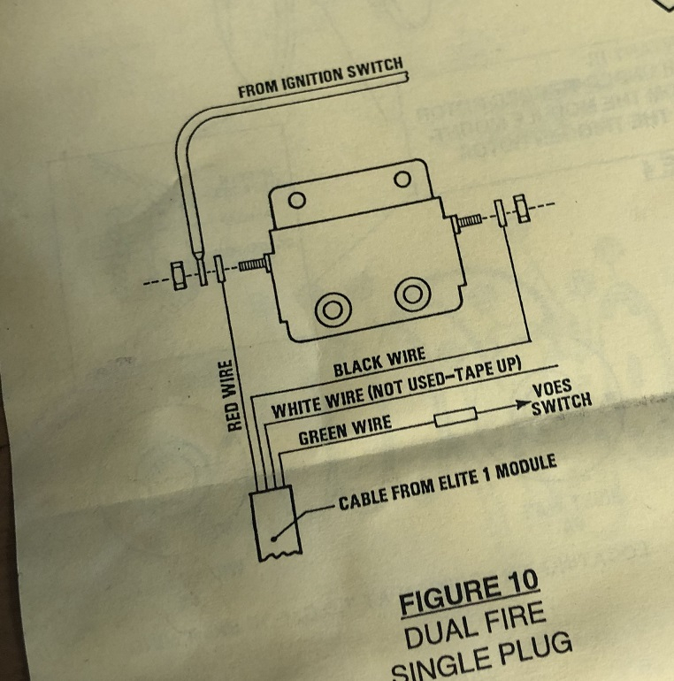
The black-and-white-striped wire from the harness goes to the negative terminal. The terminal for the negative is served by the black trace that’s attached to the white wire. The black wire connects to the contactbreaker. To check the connection, use a paperclip or a pencil to pull them out from the plug housing. It’s also crucial to make sure the terminals don’t bend.
Accessory terminals
Diagrams of ignition wiring show the different wires that are used to power the car’s various components. There are generally four colors of terminals connected to each part. The red color is for accessories, yellow to the battery, and green for the starter solenoid. The “IGN” terminal can be used to start the car, turn on the wipers, as well as other functions. This diagram demonstrates how to connect ACC and ST terminals with the rest of components.
The battery is connected to the terminal called BAT. The battery is essential for the electrical system to start. Additionally, the switch will not start without the battery. A wiring diagram can inform you where to find your car’s battery. The accessory terminals of your car are connected to the battery and the ignition button. The BAT terminal is connected to the battery.
Some ignition switches offer an additional “accessory position” that allows users to adjust their outputs independently of the ignition. Sometimes, users want to make use of an additional output that is not connected to the ignition. In order for the auxiliary output be used, wire the connector to the same shade as the ignition. Then connect it with the ACC end of the switch. Although this is a fantastic feature, there’s one thing you should know. Most ignition switches are set to have an ACC position when the car is in the ACC position, whereas they’re in the START position when the car is in the IGN position.
Gallery of Dyna Dual Fire Ignition Wiring Diagram

Gallery of Dyna Dual Fire Ignition Wiring Diagram


