Emgo Universal Ignition Coil Wiring Diagram – The first step is to take a look at the different kinds of terminals for the ignition switch. These are the terminals for the Ignition, Coil, or Accessory. Once we know the terminals used, we can begin to identify the different components of the Emgo Universal Ignition Coil Wiring Diagram. We will also cover the functions of both the Ignition Switch and the Coil. After that, we will concentrate on the accessories terminals.
Terminals for ignition switches
There are three switches in an ignition switch, which transmit the battery’s current voltage to several different destinations. The ON/OFF setting of the switch that controls the ignition is managed by the first switch, which delivers power to the choke when it’s pulled. Different manufacturers have distinct color-coding systems that correspond to the conductors. OMC follows this procedure. A connector can be added to the ignition switch to connect an electronic Tachometer.
Even though many ignition switch terminals don’t appear in their original configuration, the numbering may not match that of the diagram. Check the continuity of the wires first to ensure that they’re properly connected to the ignition switch. A multimeter is an excellent instrument to verify the continuity. When you’re satisfied with the continuity of your wires, you’ll be able to connect the new connector. If your car has an original factory-supplied ignition switch (or wiring loom), the wiring loom may differ from that in the car.
It is essential to know the ways in which the ACC outputs and the auxiliary outputs function in order to connect them. The ACC/IGN terminals function as the default connection on the ignition switch. The START/IGN terminals connect to the radio or stereo. The ignition switch acts as the engine’s switch to turn off or on. Older vehicles are identified with the letters “ACC”, “ST”, (for individual magneto cables) at their ignition switch terminals.
Terminals for coil
The first step in determining the kind of ignition coil is to comprehend the terminology that is used. A basic diagram of the wiring will reveal a variety of terminals and connections. The coils are equipped with a particular operating voltage. The initial step to determine which one you’ve got is to check the voltage at S1, the primary terminal. S1 must be checked for resistance to determine if the coil belongs to Type A, B, or C.
The chassis’ negative needs to be connected to the low-tension side. It is also the ground in the diagram of ignition wiring. The high-tension supply supplies the spark plugs with positive electricity directly. It is essential for suppression purposes that the metallic body of the coil is connected to its chassis however, it is not necessary. The wiring diagram will depict the connection between positive and negative coils. Sometimes, a malfunctioning ignition coil can be detected through a scan performed at an auto parts shop.
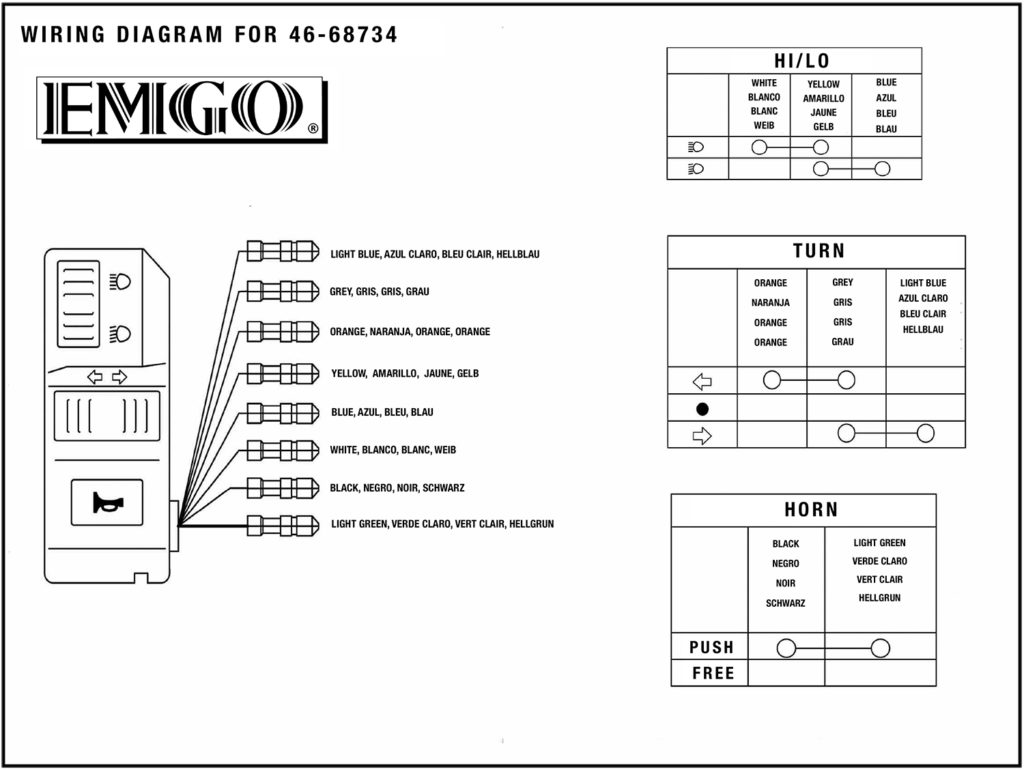
The black-and-white-striped wire from the harness goes to the negative terminal. Positive terminal receives a white wire that includes a black trace. The black wire connects to the contact breaker. If you’re not sure about the connections between the twowires, use an old paper clip to take them from the plug housing. You should also check to see that the terminals are not bent.
Accessory terminals
Diagrams of ignition wiring depict the wires that supply power to different parts of the vehicle. There are generally four terminals with color codes that are connected to each component. Red refers to accessories, yellow to the battery, and green is the starter solenoid. The “IGN” terminal is used to start the car , and also to operate the wipers as well as other operational functions. This diagram shows how to connect ACC and ST terminals with the other components.
The battery is connected to the terminal called BAT. The electrical system will not start when the battery isn’t connected. Additionally, the switch will not turn on without the battery. To locate your car’s battery look over your wiring diagram. The accessory terminals of your vehicle are connected to the battery as well as the ignition switch. The BAT terminal is connected to the battery.
Some ignition switches are equipped with an accessory position. This lets users connect their outputs to a different place without having to turn on the ignition. Sometimes, customers may wish to utilize the auxiliary input separately from the ignition. You can use the additional output by connecting it to an ACC terminal on your switch with the same colors. Although this is a great option, there’s a thing to be aware of. The majority of ignition switches have an ACC position when the vehicle is in ACC however, they will be in the START position if the vehicle is IGN.
Gallery of Emgo Universal Ignition Coil Wiring Diagram
Gallery of Emgo Universal Ignition Coil Wiring Diagram


