Ford 5000 Ignition Switch Wiring Diagram – First, we will examine the various types of terminals in the ignition switch. They include terminals for the Ignition switch, Coil, and Accessory. Once we know the purpose of these terminals are We will then determine the various parts of the Ford 5000 Ignition Switch Wiring Diagram. In addition, we will discuss the functions of the Ignition switch and Coil. We will then discuss the functions of the Ignition switch as well as Coil.
Terminals for the ignition switch
An ignition switch is comprised of three switches. They feed the battery’s voltage to many different places. The ON/OFF setting of the ignition switch is controlled by the second switch, which supplies power to the choke when it’s pulled. Different manufacturers have different color-coding schemes for different conductors. We will cover this in a separate article. OMC follows this system. The connector allows for the connection of a speedometer to the ignition switch.
While most ignition switch terminals are duplicated, the numbers may not match the diagram. Before you plug in the ignition switch, ensure that you check the continuity. This can be checked with a simple multimeter. After you’re sure that all wires are in good order, you can attach the new connector. If you have a factory-supplied ignition switch the wiring loom will be distinct from the one that is used in your vehicle.
Before you can connect the ACC outputs to your car’s auxiliary outputs it is crucial to be familiar with the fundamentals of these connections. The ACC terminals as well as the IGN terminals function as the standard connections for the ignition switch. The START and IGN connections are the primary connections for stereo and radio. The ignition switch is the one that turns the engine of your car to and off. The ignition switch terminals on older vehicles are marked with the initials “ACC” as well as “ST” (for individual magneto wires).
Coil terminals
The terms used to define the kind and model of an ignition coil is the primary thing. A basic ignition wiring diagram will show a variety of terminals and connections comprising two primary and two secondaries. Each coil is operating at a certain voltage. The first step in determining which type you’re using is to examine the voltage of S1 or the primary terminal. S1 must also be inspected for resistance to determine if the coil is an A, Type B, or an A coil.
The lower-tension side of the coil needs to be connected to the chassis”negative. This is the ground of the ignition wiring. The high-tension side connects the spark plugs to a positive. The aluminum body of the coil needs to be connected to the chassis to prevent it from being smothered but isn’t required. It is also possible to see the connections between the negative and positive coil’s terminals on the diagram of the ignition wiring. Sometimes, a malfunctioning ignition coil is identified through a scan performed at an auto repair shop.
The black-and-white-striped wire from the harness goes to the negative terminal. The white wire is the other one. It has a black trace, and it connects to the positive terminal. The black wire goes to the contact breaker. To confirm the connection, use a paperclip or a pencil to remove them of the plug housing. It’s also crucial to ensure that the terminals aren’t bent.
Accessory terminals
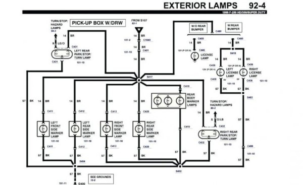
Ignition wiring diagrams depict the different wires used to power the different components. Each component has four distinct colored connections. Accessories are red and the battery yellow and the starter solenoid green. The “IGN” terminal lets you start your car, operate the wipers, or any other features that operate. The diagram below illustrates how to connect the ACC terminal as well as the ST terminals to other components.
The terminal BAT is the connection to the battery. The electrical system won’t start if the battery isn’t connected. Furthermore, the switch won’t start. It is possible to view the wiring diagram of your car to see where your car’s batteries are located. The ignition switch is connected to the car’s battery. The BAT terminal is connected to the battery.
Certain ignition switches have an independent “accessory” position, where users can control their outputs without the ignition. Customers sometimes want the output of the auxiliary to be used independently from the ignition. You can utilize the additional input by connecting the connector to the ACC terminal. This feature is convenient however it does have one significant difference. Many ignition switches can be programmed to have an ACC location when the car has been moved into the ACC position. They will also be in START mode when the vehicle has moved into the IGN position.
Gallery of Ford 5000 Ignition Switch Wiring Diagram
Gallery of Ford 5000 Ignition Switch Wiring Diagram


