Ford Duraspark Ignition Module Wiring Diagram – Let’s start by looking at the various types terminals found in an ignition switch. These terminals are used for the Ignition button, Coil and Accessory. When we have a clear understanding of the purpose of each kind of terminal, we can then identify the parts of the ignition wiring. We will also talk about the functions and the Coil. We’ll then turn our attention to the accessory terminals.
Terminals for ignition switches
There are three different switches on an ignition switch that provide the battery’s voltage to various locations. The first switch is the one that supplies the choke with power, while the second toggles the on/off state of the switch. Different manufacturers use different color-coding systems that correspond to the conductors. OMC utilizes this method. The adapter is attached to the ignition switch to allow for the addition of an tachometer.
While the majority of ignition switch terminals don’t carry an original number, they might be equipped with a different number. Check the continuity of all wires to ensure they are correctly plugged into the ignition switches. A multimeter is a good instrument to verify the continuity. Once you are satisfied that all wires are in good continuity then you can connect the new connector. If your car has an ignition switch that is installed the wiring diagram may differ.
It is important to understand how the ACC outputs and the auxiliary outputs function in order to join them. The ACC and IGN terminals are the default connections for your ignition switch, and the START and IGN terminals are the main connections for radio and stereo. The ignition switch’s function is for turning the car’s engine on and off. Older cars are identified with the letters “ACC”, “ST”, (for individual magneto cables) at the ignition switch’s terminals.
Terminals for coil
Understanding the terminology that is used is the first step in determining the kind of ignition coil to choose. There are a variety of connections and terminals on a basic ignition wiring schematic, including two primary, and two secondary. The operating voltage of every coil is different. It is essential to first check the voltage at the S1 (primary terminal). S1 must be tested for resistance in order to determine if the coil belongs to type A, B or C.
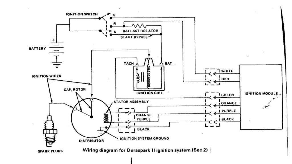
The coil with low tension must be connected at the chassis’s minus. This is what’s called the ground on the diagram of ignition wiring. The high-tension side delivers the positive power directly to the spark plugs. For suppression purposes the coil’s metal body must be connected with the chassis. It is not required to use electricity. The wiring diagram of the ignition will show you how to connect the terminals of either the positive or negative coils. In certain cases, a scan at your local auto parts store will be able to diagnose malfunctioning ignition coils.
The black-and-white-striped wire from the harness goes to the negative terminal. The white wire is black and goes to the terminal opposite. The black wire connects to the contactbreaker. To test the connections between the two wires employ a paperclip to lift them out of the housing. Be sure to verify that the connections haven’t been bent.
Accessory Terminals
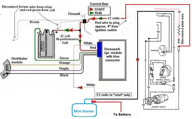
The wiring diagrams for the ignition show the different wires that provide power to the various parts of the vehicle. There are usually four colored terminals that correspond to the component. The red color represents accessories, yellow represents the battery, and green for the solenoid for starters. The “IGN terminal is used to start the car, controlling the wipers and other functions. This diagram shows how to connect ACC and ST terminals with the other components.
The terminal known as BAT is the location where the battery is. The electrical system won’t start if the battery isn’t connected. In addition the switch isn’t turned on. It is possible to refer to your wiring diagram if unsure where your car’s batteries are located. The accessory terminals of your vehicle are connected to the battery and the ignition switch. The BAT terminal connects to the battery.
Some ignition switches come with an additional “accessory” position, in which users can manage their outputs with no ignition. Users may wish to use the auxiliary output independently of the ignition. The auxiliary output could be utilized to connect the connector with the same colors as your ignition, and then connecting it to the ACC terminal of the switch. While this is an excellent feature, there’s something to be aware of. The majority of ignition switches are set up to show an ACC status when the vehicle is at the ACC or START positions.
Gallery of Ford Duraspark Ignition Module Wiring Diagram
Gallery of Ford Duraspark Ignition Module Wiring Diagram


