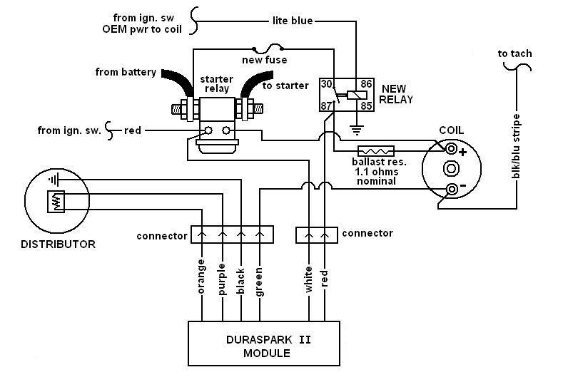
Ford Duraspark Ignition Wiring Diagram – First, we will examine the different types of terminals for the ignition switch. They are the terminals used for Coil, Ignition Switch, and Accessory. Once we have established the purpose of these terminals are for We will then discover the various components of the Ford Duraspark Ignition Wiring Diagram. We’ll also go over the functions of the Ignition switch and Coil. Then, we’ll focus to the accessory terminals.
Terminals for ignition switch
There are three switches in an ignition switch, which feed the battery’s voltage to various places. The first one supplies power to the choke whenever pushed, and the second is the position of the ignition switch’s ON/OFF. Different manufacturers have different color-coding schemes to identify different conductors. We will cover this in a separate article. OMC follows the same system. The ignition switch also includes an option to connect the timer.
Although most ignition switch terminals are duplicated, the numbers might not match the diagram. Examine the continuity of the wires first to make sure they’re properly connected to the ignition switch. You can do this with an inexpensive multimeter. Once you are satisfied that all wires are running in good harmony and you are able to connect the new connector. If your vehicle has an original factory-supplied ignition switch (or an electrical loom), the wiring loom may differ from the one in your vehicle.
Before you can connect the ACC outputs to your car’s auxiliary outputs, it is important to know the fundamentals of these connections. The ACC, IGN and START terminals are the primary connections to the ignition switch. They also function as the primary connections to your radio and stereo. The ignition switch is the one that turns the car’s engine to and off. On older cars the ignition switch’s terminals are identified with the letters “ACC” and “ST” (for distinct magnetic wires).
Terminals for coil
To figure out the type of ignition coil, the initial step is to understand the terms. A basic diagram of the wiring will reveal a variety of connections and terminals. It is essential to identify the type of coil that you are using by testing the voltage at the primary terminal, called S1. You should also test S1 for resistance to determine whether it is an A or B coil.
The negative end of the chassis should be connected to connect the coil’s low-tension end. This is what is known as the ground for the ignition wiring. The high-tension side delivers the positive power direct to the spark plugs. To prevent noise the coil’s body metal is required to be connected to the chassis. It is not required for electrical use. The wiring diagram of the ignition will show you how to connect the two terminals of the positive and negative coils. You may find an issue with the ignition coil that can be easily diagnosed by looking it up at the auto parts shop.
The black-and-white-striped wire from the harness goes to the negative terminal. The white wire is black-colored and goes to the negative terminal. The contact breaker is linked to the black wire. To verify the connection, employ a paperclip, or a pencil to lift them out of the plug housing. It’s also essential to make sure the terminals aren’t bent.
Accessory terminals
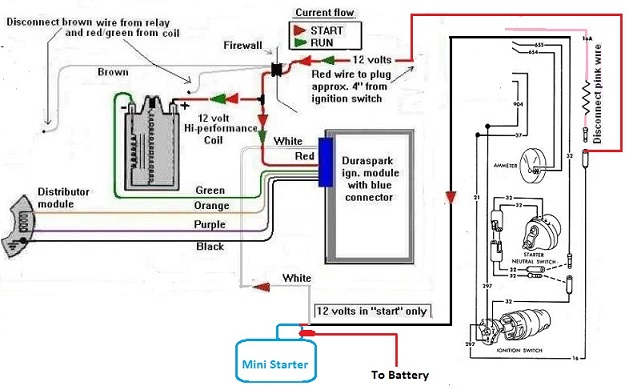
Diagrams of ignition wiring illustrate the wiring used to supply power to different parts of the vehicle. There are typically four different colored terminus lines for each component. The red color is used for accessories, yellow is for the battery, while green is for the starter solenoid. The “IGN terminal” is used to power the wipers as well as other operating features. This diagram shows how to connect ACC and ST terminals to the rest of the components.
The battery is connected to the terminal called BAT. The electrical system won’t start without the battery. Also, the switch won’t start without the battery. You can refer to your wiring diagram if not sure where the batteries of your car are. The accessory terminals in your car connect to the battery and the ignition switch. The BAT Terminal is connected to the battery.
Some ignition switches feature the “accessory” setting that allows users to regulate their outputs without needing to turn on the ignition. Some customers might want to utilize the auxiliary input independently of the ignition. Make use of the secondary output by connecting it to the ACC terminal on your switch that has the same color. Although this is a useful option, there’s an significant difference. The majority of ignition switches are configured to have an ACC status when the car’s in the ACC or START positions.
Gallery of Ford Duraspark Ignition Wiring Diagram
Gallery of Ford Duraspark Ignition Wiring Diagram


