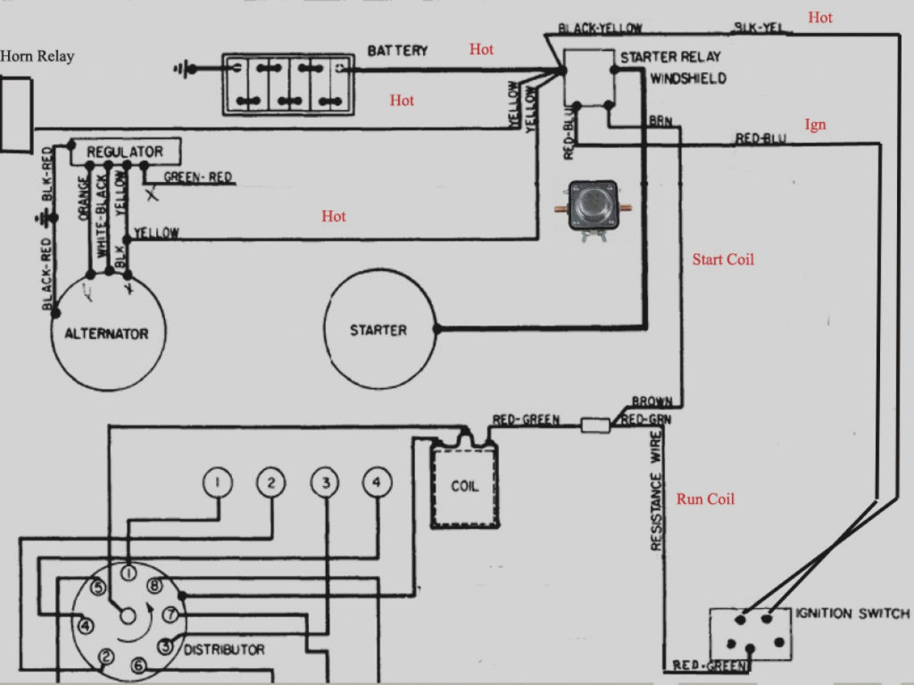
Ford Falcon Ignition Switch Wiring Diagram – The first step is to take a look at the different kinds of terminals on the ignition switch. They include terminals for the Ignition switch, Coil, and Accessory. After we’ve identified what these terminals do then we can be able to identify the various parts of the ignition wiring. Then, we will discuss the roles of the Ignition switch as well as the Coil. Following that, we will proceed to the Accessory Terminals.
Ignition switch terminals
An ignition switch has three switches. They transmit the voltage of the battery to different places. The ON/OFF state of the switch that controls the ignition is managed by the third switch, which provides power to the choke whenever it is pushed. Every manufacturer has its individual color-coding system that we’ll go over in a separate article. OMC uses this method. A connector is also included in the ignition switch for connecting the tachometer.
Although the majority of ignition switch terminals can be duplicated, the numbers may not be in line with the diagram. Check the electrical continuity to ensure that they are connected to the ignition switch correctly. You can do this with an inexpensive multimeter. Once you are satisfied that the wires are running in good harmony and you are able to connect the new connector. If your car is equipped with an original ignition switch supplied by the factory (or wiring loom) The wiring loom might differ from the one in your vehicle.
To connect the ACC outputs to the auxiliary outputs of your vehicle, you have to understand the way these two connections function. The ACC and IGN terminals are the default connections for the ignition switch. the START and IGN terminals are the primary connections for stereo and radio. The ignition switch switches the car’s engine ON and OFF. Older vehicles are identified with the initials “ACC”, “ST”, (for individual magneto cables) on their ignition switch’s terminals.
Terminals for coil
The first step to determine the kind of ignition coil is to know the terminology that is used. In a basic ignition wiring diagram you’ll see various connections and terminals, which include two primary and two secondary. The coils have a specific operating voltage, and the first method of determining what type you’ve got is to check the voltage at S1, the primary terminal. S1 should also be tested for resistance to determine if the coil is a Type B, B or an A coil.
The chassis’ negative needs to be connected to the side of low-tension. This is also the ground on the diagram of ignition wiring. The high-tension side delivers positively direct to the spark plugs. The aluminum body of the coil needs to be connected to the chassis for suppression, but it isn’t electrically required. The wiring diagram will also show the connection between the positive and negative coil terminals. In certain cases it is recommended to conduct a scan at your local auto parts shop will be able to diagnose malfunctioning ignition coils.
The black-and-white-striped wire from the harness goes to the negative terminal. The negative terminal is served by the black trace attached to the white wire. The black wire connects to the contact breaker. You can examine the connections with a pencil to remove the wires from the housing. Check that you don’t bend the connectors.
Accessory terminals
Diagrams of the ignition wiring illustrate the wires that power various parts of the vehicle. There are usually four different colored terminals for each component. The accessories are colored red and the battery yellow and the starter solenoid green. The “IGN terminal is used for starting the vehicle, controlling the wipers and other functions. The below diagram shows how to connect both the ACC terminal and ST terminals to other components.
The terminal BAT holds the battery. The electrical system will not start without the battery. Additionally, the switch won’t begin to turn on. If you don’t know the location of your car’s battery located, you can look at your wiring diagram to figure out how to locate it. The ignition switch is linked to the car’s battery. The BAT terminal connects to the battery.
Some ignition switches feature an independent “accessory” position, where users can manage their outputs without using the ignition. Customers may want to utilize the auxiliary output in addition to the ignition. The auxiliary output could be connected to connect the connector with the same color as your ignition, and then connecting it to the ACC terminal of the switch. Although this is a fantastic feature, there’s one thing you should know. A majority of ignition switches feature an ACC position when the car is in ACC mode and a START mode when you are in IGN.
Gallery of Ford Falcon Ignition Switch Wiring Diagram
Gallery of Ford Falcon Ignition Switch Wiring Diagram


