Ford Ikon Ignition Coil Wiring Diagram – Let’s begin by looking at the different types of terminals on an ignition switch. These are the terminals used for Coil, Ignition Switch, and Accessory. Once we’ve established the purpose of the terminals it is possible to determine the various components of the ignition wiring. In addition, we will discuss the functions of the Ignition switch and Coil. After that we will discuss the Accessory Terminals.
The terminals of the ignition switch
The ignition switch has three switches. They transmit the voltage of the battery to different locations. The ON/OFF position of the switch that controls the ignition is managed by the first switch, which delivers power to the choke when it’s pulled. Each manufacturer has its own color-coding system, which we will discuss in another article. OMC uses this system. The ignition switch also includes an adapter for the addition of a timer.
Even though some of the ignition switch terminals might not be original, the numbers of each may not be in line with the diagram. Check the integrity of the wires first to ensure that they’re connected correctly to the ignition switch. A multimeter is an excellent instrument to verify the continuity. Once you’ve verified the continuity of the wires you are able to install the connector. The wiring loom used in an ignition system switch that is supplied by the manufacturer differs.
For connecting the ACC outputs to the auxiliary outputs on your car, you need first know how these two connections work. The ACC/IGN terminals function as the default connections on the ignition switch. The START/IGN terminals connect to the stereo or radio. The ignition switch turns the car’s engine on and off. Older vehicles have ignition switch terminals marked “ACC” or “ST” (for individual magnetowires).
Terminals for coil
To determine the type of ignition coil you need to know the step is to know the terminology. You’ll see a number of connections and terminals in a basic ignition wiring schematic, including two primary, as well as two secondary. The coils are equipped with a particular operating voltage. The first method of determining what type you’re using is to test the voltage on S1, the main terminal. S1 should also be checked for resistance in order to identify if the coil is an A, Type B, or an A coil.
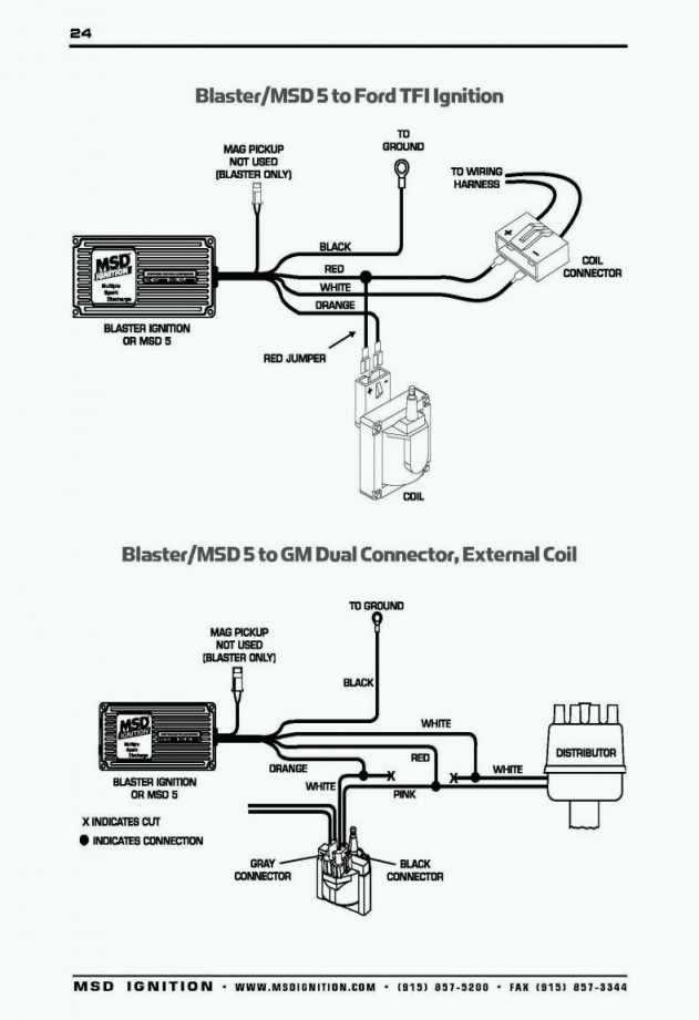
The chassis’ negative end should be connected to connect to the coil’s lower-tension end. This is what’s called the ground on the ignition wiring diagram. The high-tension part provides positive direct to the sparkplugs. For suppression purposes the body of the coil must be connected to chassis. But, it’s not necessary to electrically connect. The diagram of the ignition wiring will also show the connections of the positive coil’s terminals. In some cases, a scan at the local auto parts store can help you identify malfunctioning ignition coils.
The black-and-white-striped wire from the harness goes to the negative terminal. The white wire also is black with a trace on it, and it goes to the positive terminal. The black wire is connected to the contact breaker. It is possible to remove the black wire from the plug housing with a paper clip If you’re unsure of the connections. It is also important to see that the terminals aren’t bent.
Accessory terminals
Diagrams of ignition wiring show the wires that power various parts of the car. There are generally four colored terminals for each component. Red is used for accessories and yellow is for the battery, and green is the solenoid for starters. The “IGN” terminal is used to start the vehicle, controlling the wipers and other functions. This diagram demonstrates how to connect ACC and ST terminals to the other components.
The terminal BAT is the connector for the battery. The electrical system will not start if the battery isn’t connected. Additionally the switch isn’t turned on. To find your car’s battery, check your wiring diagram. The ignition switch as well as the battery are connected through the accessory terminals. The BAT terminal is connected to the battery.
Some ignition switches feature an additional “accessory” position, where users can manage their outputs without using the ignition. Sometimes, customers want to use the auxiliary output separate from the ignition. In order for the auxiliary output be used, plug in the connector with the same shade as that of the ignition. Then connect it with the ACC end of the switch. Although this is a useful feature, there’s one significant difference. Many ignition switches have an ACC position when your car is in ACC mode and a START position when you are in IGN.
Gallery of Ford Ikon Ignition Coil Wiring Diagram
Gallery of Ford Ikon Ignition Coil Wiring Diagram


