Gsxr 750 Ignition Wiring Diagram – We will first look at the various types of terminals for the ignition switch. These are the terminals for the Ignition, Coil, or Accessory. When we have a clear understanding of the purpose of each type of terminal, we can then identify the parts of the ignition wiring. Then, we will discuss the functions and the Coil. Following that, we will discuss the Accessory Terminals.
The terminals of the ignition switch
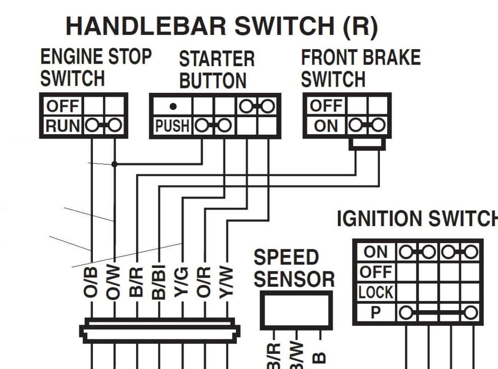
An ignition switch has three switches. They feed the battery’s voltage to different locations. The first switch is utilized to turn on the choke through pushing it, and another switch controls the ON/OFF setting. Different manufacturers have distinct colors-coding systems to match the conductors. OMC uses this method. The adapter is attached to the ignition switch, allowing the installation of a tachometer.
Although the majority of ignition switch terminals can be duplicated, the number may not be consistent with the diagram. Before plugging in the ignition switch, be sure to test the continuity. This can be checked with a multimeter that is inexpensive. After you’re sure that all wires are in good continuity then you can connect the new connector. If your car has an ignition switch installed the wiring diagram will differ.
Knowing how the ACC outputs connect to the auxiliary outputs of your car is essential. The ACC and IGN connectors are the standard connections for the ignition switch. While the START, IGN, and ACC terminals are the primary connections for radios or stereo, the START/IGN terminals are the main ones. The ignition switch’s function is for turning the car’s engine on and off. On older cars the terminals of the ignition switch are identified with the letters “ACC” and “ST” (for individual magnetic wires).
Terminals for coil
Understanding the terms is the initial step towards finding out what kind of ignition coil you’ve got. The basic ignition wiring diagram shows a number different connections and terminals. There are two primary and secondary connections. Each coil is operating at a certain voltage. The first step to determine which kind of coil you’re using is to examine the voltage on S1, or the primary terminal. S1 should also undergo resistance testing to determine whether it’s a Type A or B coil.
The negative end of the chassis should be connected to the coil’s low-tension end. It is also the ground on the diagram of ignition wiring. The high-tension side delivers positive direct to the spark plugs. The body of the coil has to connect to the chassis to prevent it from being smothered, but it is not electrically essential. You will also see the connections between the positive and the negative coil terminals on the ignition wiring diagram. Sometimes, a check at an auto parts store could identify a problem with the ignition wire.
The black-and-white-striped wire from the harness goes to the negative terminal. The other white wire is black and connects to the terminal opposite. The black wire is connected to the contact breaker. To test the wires’ connections, employ a paperclip to lift them off the housing. It’s also crucial to ensure that the terminals aren’t bent.
Accessory terminals
The diagrams for ignition wiring illustrate the wires used to power the vehicle’s electrical supply. Each component is equipped with four distinct colored connections. The red color represents accessories, yellow for the battery, and green for the starter solenoid. The “IGN terminal is used to start the vehicle, controlling the wipers and other functions. The diagram below illustrates how to connect the ACC terminal as well as the ST terminals to the other components.
The battery is attached to the terminal whose name is BAT. The electrical system can’t be started without the battery. A dead battery could cause the switch to not come on. The wiring diagram will inform the location of the battery of your car. The ignition switch is connected to the car’s battery. The BAT connector connects to your battery.
Some ignition switches are equipped with an additional position. It allows users to connect their outputs to a different location without having to turn on the ignition. In some cases, users may want to use the auxiliary output separately from the ignition. You can utilize the secondary input by connecting it to the ACC terminal. While this is a convenient feature, there’s one significant difference. The majority of ignition switches are set up to have an ACC status when the vehicle is in either the ACC or START positions.
Gallery of Gsxr 750 Ignition Wiring Diagram
Gallery of Gsxr 750 Ignition Wiring Diagram


