Gy6 Ignition Switch Wiring Diagram – First, we will examine the different types of terminals on the ignition switch. These terminals include the Ignition switch and Coil as well as the Accessory. Once we know what these terminals do then we can be able to identify the various parts of the ignition wiring. We will also discuss the functions of the Ignition switch and Coil. Next, we’ll discuss the roles of the Ignition switch and Coil.
Terminals for ignition switch
There are three separate switches in the ignition switch, and they transmit the battery’s current voltage to several different locations. The first switch powers the choke. The second switch controls the ON/OFF of the ignition switch. Different manufacturers have their own color-coding system for the various conductors, which is documented in another article. OMC follows this system. An additional connector is included inside the ignition switch to allow attaching a Tachometer.
While most ignition switch terminals are not original, the numbering for each one may not be in line with the diagram. Check the continuity of all wires to make sure they’re properly connected to the ignition switches. You can check this using an inexpensive multimeter. Once you are satisfied with the continuity of the wires, connect the new connector. The wiring loom of an ignition switch that’s factory-supplied will be different than the one that you have in your vehicle.
It is important to know the differences between the ACC and secondary outputs. The ACC and IGN terminals are the default connection on your ignition switch, and the START and IGN terminals are the main connections for stereo and radio. The ignition switch is the engine’s switch to turn off or on. The terminals of the ignition switch on older cars are identified with the letters “ACC” and “ST” (for each magneto wires).
Terminals for Coil
To figure out the type of ignition coil, the initial step is to learn the definition of. A basic diagram of the wiring will provide you with a range of connections and terminals. Each coil is equipped with a distinct operating voltage. To determine the type of coil you own, the first step is to test the voltage at S1, which is the primary terminal. S1 should also undergo resistance testing to determine if it are a Type A or B coil.
The chassis’ negative should be connected to connect the coil’s low-tension end. This is the ground of the ignition wiring. The high-tension end provides positive direct to the sparkplugs. To prevent noise the coil’s metal body is required to be connected to the chassis. This is not necessary for electrical use. There are also connections of the positive and negative coil’s terminals on an diagram of the ignition wiring. You may find an issue with the ignition coil that can be easily diagnosed by looking it up at an auto parts retailer.
The black-and-white-striped wire from the harness goes to the negative terminal. The terminal that is negative is served by the trace in black that’s joined to the white wire. The black wire connects to the contact breaker. You can check the connections with a paperclip to take the wires out from the housing. Check that the terminals aren’t bent.
Accessory terminals
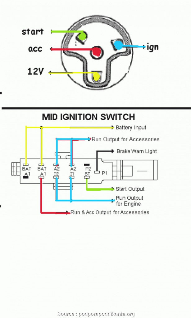
The ignition wiring diagrams illustrate the different wires that are used to power various components of the car. In general, there are four different color-coded terminals for each component. The red color is used for accessories and yellow is for the battery, and green is for the solenoid for starters. The “IGN terminal is used for starting the car, controlling the wipers and various other functions. The following diagram shows how to connect both the ACC terminal as well as the ST terminals to various components.
The terminal BAT is where the battery is. The battery is essential for the electrical system to begin. The switch also won’t turn on without the battery. You can view your wiring diagram to determine where your car’s batteries are located. The ignition switch and battery are connected by the accessory terminals. The BAT connector connects to your battery.
Certain ignition switches come with an accessory setting where users can modify their outputs and manage them without needing to use the ignition. Sometimes, customers may wish to use the auxiliary output separately from the ignition. To use the auxiliary output, connect the connector with identical colors to the ignition and connect it to the ACC terminal on the switch. This is an excellent feature, however there’s one important difference. Many ignition switches have the ACC position when your car is in ACC mode and a START position when the switch is in IGN.
Gallery of Gy6 Ignition Switch Wiring Diagram
Gallery of Gy6 Ignition Switch Wiring Diagram


