Harley Davidson Ignition Wiring Diagram – Let’s start by looking at different kinds of terminals that are found on the ignition switch. These terminals are for the Ignition button, Coil and Accessory. After we’ve established what these kinds of terminals are used for We will then determine the various parts of the Harley Davidson Ignition Wiring Diagram. We’ll also discuss the functions of both the Ignition Switch and Coil. The next step is to focus to the accessory terminals.
Terminals for ignition switch
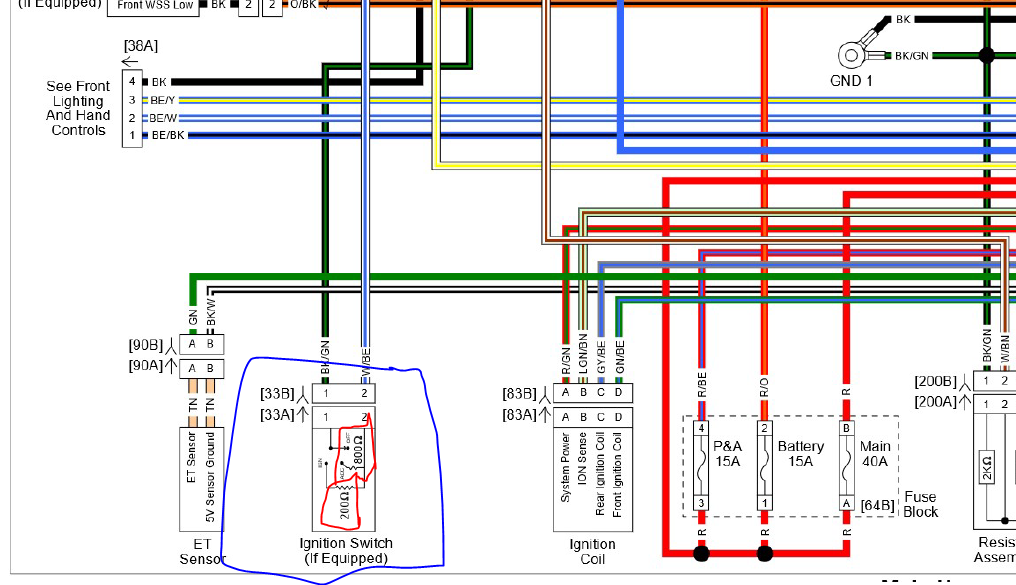
Three switches are found on the ignition switch. Each of these switches is able to feed the battery’s voltage to several different places. The first is used to drive the choke through pushing it, while the third switch is used to control the ON/OFF position. Each manufacturer has its individual color-coding system that we will discuss in another article. OMC utilizes this system. The ignition switch also includes a connector for adding an Tachometer.
Even though many ignition switch terminals do not come in original form however, the numbers may not match the diagram. Check the continuity of the wires first to ensure they’re properly connected to the ignition switch. This can be checked with a multimeter that is inexpensive. After you’re satisfied with the integrity of the wires install the new connector. If you are using an ignition switch supplied by the manufacturer the wiring loom may be different from the one in your car.
Knowing how the ACC outputs connect to the auxiliary outputs in your car is vital. The ACC terminals as well as the IGN terminals serve as the standard connections for the ignition switch. The START and IGN connections are the most important connections for stereo and radio. The ignition switch is the engine’s off/on button. Older cars have the ignition switch terminals marked “ACC” or “ST” (for individual magnetowires).
Terminals for coil
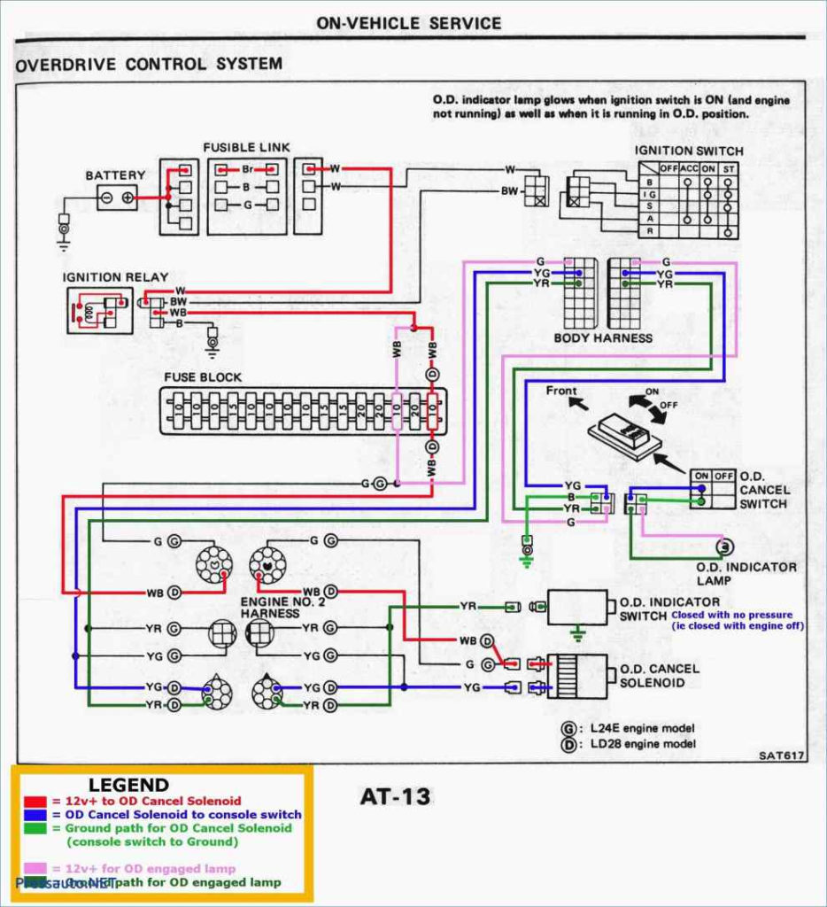
The first step in determining the type of ignition coil is to understand the terminology used. A basic diagram of the wiring will reveal a variety of terminals and connections. The coils are equipped with a particular operating voltage, and the first step to determine which one you’ve got is to check the voltage on S1, the primary terminal. S1 must also go through resistance testing to determine if it is an A or B coil.
The coil’s low-tension side is to be connected to the chassis’ positive. This is what’s called the ground in the diagram of the ignition wiring. The high tension side provides positively directly to the spark plugs. The coil’s aluminum body needs to be linked to the chassis to prevent it from being smothered but isn’t required. The wiring diagram for ignition will also show the connection of the positive coil terminals. Sometimes, a malfunctioning ignition coil is identified by a scan done at an auto repair shop.
The black-and-white-striped wire from the harness goes to the negative terminal. The terminal that is negative is served by the black trace that’s attached to the white wire. The black wire connects to the contact breaker. You can examine the connections with a paperclip to remove the wires from the housing. Be sure that the terminals aren’t bent.
Accessory terminals
Diagrams of ignition wiring depict the wires used to power various parts of the vehicle. Each component has four distinct connections that are color coded. The red color represents accessories, yellow is for the battery and green is for the starter solenoid. The “IGN terminal” is used to provide power to the wipers and other operating functions. The diagram illustrates the connection of the ACC- and ST terminals.
The battery is connected to the terminal named BAT. Without the battery, the electrical system does not start. In addition, the switch doesn’t turn on. To find the battery in your car examine the wiring diagram. The accessory terminals on your car connect to the battery and the ignition switch. The BAT terminal is connected to the battery.
Some ignition switches feature a separate “accessory” position, where users can manage their outputs without the ignition. Some customers may prefer to use the auxiliary output separately from the ignition. In order to use the auxiliary output, wire the connector with identical colors to the ignition and connect it to the ACC terminal on the switch. While this is an excellent feature, there is one important difference. Many ignition switches have the ACC position when your car is in ACC mode, and a START position when the switch is in IGN.
Gallery of Harley Davidson Ignition Wiring Diagram
Gallery of Harley Davidson Ignition Wiring Diagram


