Honda Civic Ignition Wiring Diagram – First, we will examine the various types of terminals found on the ignition switch. They include terminals for the Ignition switch, Coil, and Accessory. Once we’ve established the purpose of the terminals it is possible to recognize the various parts of the ignition wiring. In addition, we will discuss the different functions of the Ignition Switch and Coil. Following that, we’ll shift our attention to the Accessory terminals.
Terminals for ignition switches
There are three separate switches in the ignition switch, and they feed the battery’s voltage to various locations. The first switch powers the choke. The second switch is responsible for the ON/OFF of the ignition switch. Different manufacturers utilize their own color-coding method for the various conductors, which is explained in a different article. OMC follows the same system. The ignition switch is also equipped with an adapter for the addition of a timer.
While many ignition switch terminals might not be original, the numbers of the terminals may not be in line with the diagram. Before plugging into the ignition switch ensure that you check the continuity. You can do this with a simple multimeter. Once you’re satisfied with the quality of the connection it’s time to connect the new connector. If you are using an ignition switch that is supplied by the manufacturer the wiring loom may be different from that in your car.
Understanding how ACC outputs are connected to the auxiliary outputs in your vehicle is crucial. The ACC and IGN terminals are the default connection on the ignition switch. the START and IGN terminals are the primary connections for stereo and radio. The ignition switch’s function is to turn the car’s engines on and off. Older cars have the ignition switch terminals labeled “ACC” or “ST” (for individual magnetowires).
Terminals for coil
The first step in determining the type of ignition coil is to understand the terms employed. A simple diagram of the wiring will reveal a variety of terminals and connections, comprising two primary and two secondaries. Each coil operates at a specific voltage. The first step to determine the type you’re using is to examine the voltage at S1 or the primary terminal. It is also recommended to examine S1 for resistance to determine whether it is a Type A, B, or C coil.
The chassis’ negative needs to be connected to the side of low-tension. It is also the ground on an ignition wiring diagram. The high-tension component supplies positive direct to the spark plugs. For suppression purposes the body of the coil is required to be connected to the chassis. It is not required to connect electrically. The diagram of the ignition wiring will also reveal the connections between the positive and negative coil’s terminals. In certain cases, a scan at your local auto parts store will be able to diagnose defective ignition coils.
The black-and-white-striped wire from the harness goes to the negative terminal. The white wire is the other one. It has a black trace, and connects to the positive terminal. The black wire connects to the contact breaker. You can remove the black wire from the plug housing with a paper clip If you’re unsure of the connection. It is also important to ensure that the terminals are not bent.
Accessory Terminals
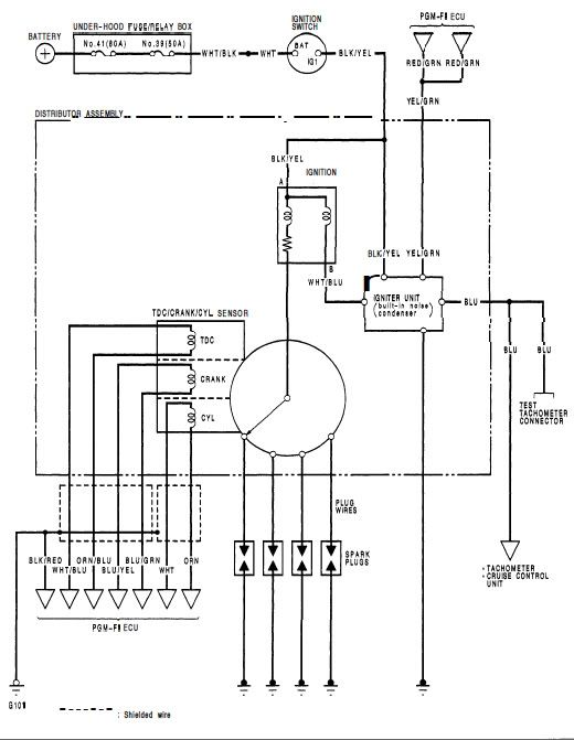
Diagrams of ignition wiring depict the wiring used in the power supply of the vehicle. Typically, there are four different color-coded terminals for each component. Red is for accessories, yellow is for the battery, while green is the starter solenoid. The “IGN” terminal can be used to start the car, operate the wipers, and other features. The diagram illustrates how to connect ACC or ST terminals as well as the rest.
The terminal called BAT is the place where the battery is. The electrical system will not start without the battery. A dead battery could make the switch not come on. A wiring diagram can show the location of the battery in your car. The ignition switch is connected to the car’s battery. The BAT terminal connects to the battery.
Some ignition switches feature an “accessory” position that allows users to regulate their outputs without having to use the ignition. Sometimes, customers want to make use of an additional output independent of the ignition. Make use of the secondary output by connecting the connector to the ACC terminal on your switch with the same colors. This is a great feature, however there’s an important distinction. A lot of ignition switches can be set to have an ACC location when the car has moved into the ACC position. They’ll also be in START mode after the vehicle has been moved into the IGN position.
Gallery of Honda Civic Ignition Wiring Diagram
Gallery of Honda Civic Ignition Wiring Diagram


