Honda Grom Ignition Wiring Diagram – The first step is to take a look at the different types of terminals that are used in the ignition switch. These terminals comprise the Ignition switch as well as the Coil along with the Accessory. Once we have identified the terminals used, we can begin to determine the various components of the Honda Grom Ignition Wiring Diagram. We’ll also be discussing the functions of the Ignition switch, as well as the Coil. The next step is to focus to the accessory terminals.
The ignition switch’s terminals
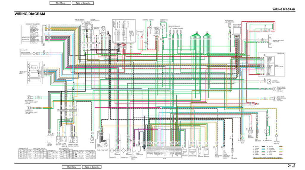
Three switches are located on an ignition switch. Each of the three switches feeds the battery’s voltage to several different places. The first is used to turn on the choke through pushing it, and the third switch is used to control the ON/OFF setting. Different manufacturers use their own color-coding systems for the various conductors, that is described in a separate article. OMC utilizes this method. There is a connector in the ignition switch to allow attaching a Tachometer.
Although the majority of ignition switch terminals can be duplicated, the numbers may not be in line with the diagram. To make sure that the wires are correctly plugged in to the ignition switch you should check their continuity. A multimeter is a great tool to test the continuity. Once you’re satisfied about the continuity of your wires, you’ll be able to install the new connector. If your vehicle has an original factory-supplied ignition switch (or an electrical loom), the wiring loom might differ from the one in your car.
Understanding how the ACC outputs connect to the auxiliary outputs of your vehicle is crucial. The ACC and IGN terminals are the default connections on your ignition switch, and the START and IGN terminals are the principal connections for radio and stereo. The ignition switch controls the car’s engine. The ignition switch terminals on older cars are identified with the initials “ACC” as well as “ST” (for each magneto wires).
Terminals for coil
The first step in determining the type of ignition coil is to comprehend the terms employed. In a typical diagram of the wiring for ignition there are various terminals and connections, including two primary and two secondary. Each coil has a specific operating voltage. To determine the type of coil you have the first step is to test the voltage at S1, the primary terminal. S1 should be checked for resistance to determine if the coil belongs to Type A, B, and/or C.
The coil’s low-tension side should be connected to the chassis’ plus. This is what’s called the ground in the ignition wiring diagram. The high-tension part supplies positive direct to the sparkplugs. It is necessary to suppress the body of the coil’s metal be connected to the chassis, however it isn’t essential. You will also see the connections of the negative and positive coil’s terminals on an ignition wiring diagram. Sometimes, a visit to an auto part store can detect a defective ignition wire.
The black-and-white-striped wire from the harness goes to the negative terminal. The white wire has a black color and goes to the negative terminal. The black wire is connected to the contactbreaker. You can examine the connections using a paperclip to remove the wires from the housing. Be sure to ensure that the terminals have not been bent.
Accessory terminals
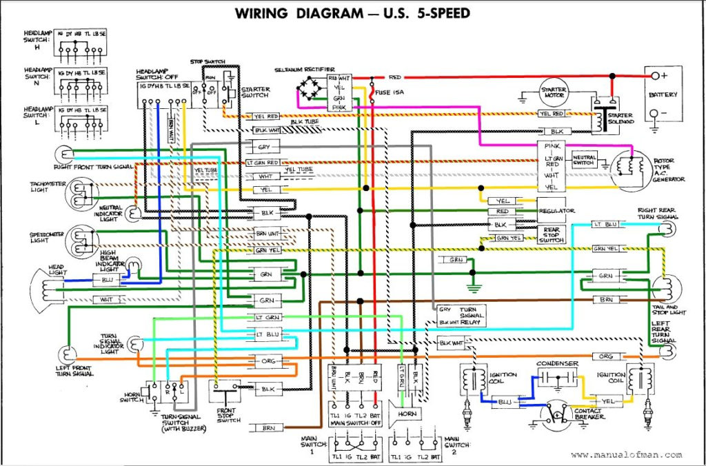
Diagrams of the ignition wiring depict the wiring used to supply power to different parts of the vehicle. In general, there are four different colors-coded terminals that are used for each component. Red refers to accessories, yellow the battery and green for the starter solenoid. The “IGN terminal lets you start the car, control the wipers, and any other operation features. The diagram illustrates how you can connect ACC or ST terminals as well as the rest.
The terminal BAT holds the battery. The battery is necessary for the electrical system to begin. Also, the switch won’t turn on without the battery. The wiring diagram will tell you the location of your car’s battery. The accessory terminals in your car are connected to the ignition switch, as well as the battery. The BAT terminal is connected to the battery.
Certain ignition switches provide an additional “accessory position” that lets users adjust their outputs independently of the ignition. Customers may want to utilize the auxiliary output separately from the ignition. To use the additional output, wire the connector using identical colors to the ignition and connect it to the ACC terminal on the switch. This is an excellent feature, but there is an important distinction. Most ignition switches are configured to show an ACC status when the car’s in the ACC or START positions.
Gallery of Honda Grom Ignition Wiring Diagram
Gallery of Honda Grom Ignition Wiring Diagram


