Honda Motorcycle Ignition Switch Wiring Diagram – Let’s first examine the different types and functions of the terminals in the ignition switches. These are terminals for the Ignition, Coil, or Accessory. After we’ve identified what these terminals are, we will identify the different parts in the ignition wiring. In addition, we will discuss the functions of the Ignition switch, and Coil. Next, we’ll discuss the roles of the Ignition switch as well as Coil.
Terminals for ignition switch
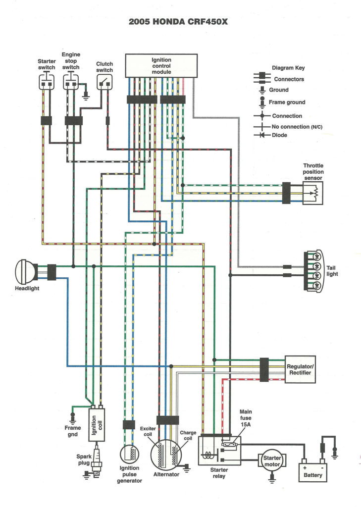
An ignition switch contains three switches that supply the battery’s power to various locations. The first switch provides power to the choke whenever it is pushed. The second is the ignition switch’s ON/OFF position. Different manufacturers utilize their own color-coding method for different conductors which is documented in another article. OMC utilizes this method. An adapter is included on the ignition switch that allows for the addition of the tachometer.
While the majority of ignition switch terminals don’t come in original form, the numbering may not be in line with the diagram. To ensure that your wires are correctly connected to the switch it is recommended to check their continuity. A multimeter is an excellent tool to check the continuity. Once you’re satisfied about the integrity of your wires, you will be able to connect the new connector. If your car is equipped with an original factory-supplied ignition switch (or a wiring loom) the wiring loom will differ from that in your vehicle.
To connect the ACC outputs to the auxiliary outputs of your vehicle, you have first know the way these two connections function. The ACC, IGN and START terminals are the primary connection to the ignition switch. They also serve as the main connections to the radio and stereo. The ignition switch acts as the engine’s switch to turn off or on. Older cars have the ignition switch terminals marked “ACC” or “ST” (for individual magnetowires).
Terminals for coil
The first step to determine the kind of ignition coil is to comprehend the terminology used. In a typical ignition wiring diagram you’ll see various connections and terminals, which include two primary and two secondary. The coils come with a distinct operating voltage, and the first method of determining what type you’re using is to test the voltage of S1 the main terminal. S1 should be checked for resistance to determine if the coil is type A, B or C.
The low-tension end of the coil should be connected to the chassis’ negative. This is what’s called the ground in the diagram of the ignition wiring. The high-tension component supplies positively directly to the spark plugs. It is required for suppression purposes that the body of the coil’s metal be connected to the chassis, but not essential. The wiring diagram will also show the connection between the positive and negative coils. In certain instances it is recommended to conduct a scan at your local auto parts store will help identify the malfunctioning ignition coils.
The black-and-white-striped wire from the harness goes to the negative terminal. The other white wire has a black trace on it and it goes to the positive terminal. The black wire connects to the contactbreaker. To check the connection, make use of a paperclip or pencil to remove them of the plug housing. Also, make sure to check that the terminals haven’t been bent.
Accessory Terminals
Ignition wiring diagrams show the various wires used to power the car’s various components. There are generally four color-coded terminals to each component. Red is for accessories and yellow is for the battery, while green is for the solenoid for starters. The “IGN terminal” is used to provide power to the wipers and other operating functions. The diagram demonstrates how to connect the ACC and ST terminals to the rest of the components.
The terminal BAT is the connection to the battery. The battery is essential for the electrical system to begin. The switch won’t be able to turn on if there is no battery there. The wiring diagram will inform you the location of your car’s battery. The accessory terminals of your car connect to the ignition switch as well as the battery. The BAT terminal is connected to the battery.
Some ignition switches offer the option of an “accessory position” that allows users to modify their outputs independent of the ignition. In some cases, users may want to utilize the auxiliary output separately from the ignition. You can utilize the additional input by connecting it to the ACC terminal. This feature is convenient however it does have one significant differentiator. Many ignition switches can be set to have an ACC location when the car is in the ACC position. They’ll also be in START mode when the vehicle has moved into the IGN position.
Gallery of Honda Motorcycle Ignition Switch Wiring Diagram
Gallery of Honda Motorcycle Ignition Switch Wiring Diagram


