Honda Small Engine Ignition Switch Wiring Diagram – The first step is to take a look at the different kinds of terminals that are used on the ignition switch. The terminals are the Ignition switch as well as the Coil and the Accessory. Once we’ve established the purpose of the terminals we will be able to identify the various parts of the ignition wiring. We’ll also discuss the functions of the Ignition switch, and Coil. Then, we’ll talk about the roles of the ignition switch and Coil.
Terminals for ignition switch
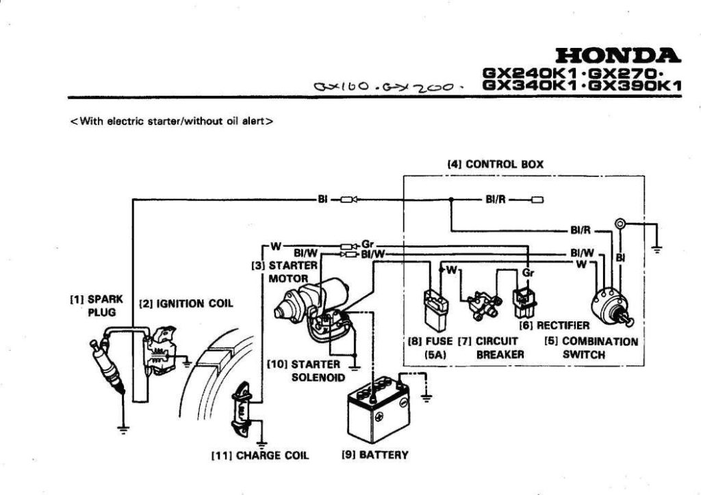
An ignition switch contains three different switches that direct the battery’s current to various locations. The first switch provides the choke with power when pushed, and the second is the switch that controls the ignition’s ON/OFF positions. Different manufacturers have their own color-coding system for the various conductors, which is documented in another article. OMC uses this method. The connector permits the attachment of a speedometer the ignition switch.
While the majority of ignition switch terminals do not have an initial number, they could have a different number. Before plugging in the ignition switch, be sure to test the continuity. This can be done using an inexpensive multimeter. Once you’re satisfied with the continuity it’s time to connect the new connector. If you have an ignition switch supplied by the manufacturer the wiring loom may be different from the one in your car.
To connect the ACC outputs to the auxiliary outputs on your car, you’ll need first know the way these two connections function. The ACC terminals as well as the IGN terminals serve as the standard connections for the ignition switch. The START and IGN connections are the primary connections for radio and stereo. The ignition switch is responsible for turning the car’s engine on and off. The terminals of the ignition switch on older cars are labeled with the initials “ACC” and “ST” (for individual magneto wires).
Coil terminals
The first step in determining the type of ignition coil is to understand the terms used. An understanding of the basic wiring diagram for ignition will reveal a variety of terminals and connections. Each coil has a specific operating voltage. To determine what kind of coil you’ve got, the first step is to determine the voltage at S1, which is the primary terminal. To determine whether it’s a Type A, C, or B coil you should also test S1’s resistance.
The chassis’ negative needs to be connected to the side of low-tension. This is also the ground on the ignition wiring diagram. The high-tension side delivers positively directly to the spark plugs. To prevent noise the body of the coil must be connected to chassis. It is not necessary to connect the coil electrically. The wiring diagram for the ignition will explain how to connect the terminals of either the negative or positive coils. Sometimes, a malfunctioning ignition coil is identified through a scan performed at an auto parts shop.
The black-and-white-striped wire from the harness goes to the negative terminal. The negative terminal is served by the black trace that’s attached to the white wire. The contact breaker is linked to the black wire. If you’re not certain about the connections between both, you can use the clip of a paperclip to remove them from the housing of the plug. Be sure that the terminals aren’t bent.
Accessory terminals
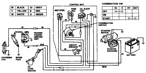
Diagrams of ignition wiring depict the wires that are used to power the vehicle’s electrical supply. In general, there are four different colored terminals for each part. Accessories are red and the battery yellow and the starter solenoid is green. The “IGN terminal” is used to provide power to the wipers along with other operational features. The diagram demonstrates how to connect the ACC and ST terminals to the other components.
The terminal BAT connects the battery to the charger. The battery is essential for the electrical system to begin. Furthermore, the switch won’t begin to turn on. It is possible to view the wiring diagram of your car to see where your car’s batteries are located. The accessory terminals of your vehicle are connected to the battery as well as the ignition switch. The BAT terminal is connected to the battery.
Some ignition switches come with the option of an “accessory position” that lets users adjust their outputs independently of the ignition. Users may wish to use the auxiliary output in addition to the ignition. In order for the auxiliary output be used, wire the connector to the same shade as that of the ignition. Connect it to the ACC end of the switch. This is a great feature, but there is one important difference. The majority of ignition switches have an ACC position when the vehicle is in the ACC however they will be in the START position when the vehicle is IGN.
Gallery of Honda Small Engine Ignition Switch Wiring Diagram
Gallery of Honda Small Engine Ignition Switch Wiring Diagram


