Ice Ignition Wiring Diagram – The first step is to take a look at the different types of terminals on the ignition switch. These are the terminals that connect the Ignition, Coil, or Accessory. Once we know the purpose of each terminal, we can then identify the various components of the ignition wiring. We will also cover the roles of both the Ignition Switch and the Coil. After that, we’ll turn our attention to the Accessory terminals.
Terminals for ignition switch
There are three separate switches on the ignition switch, and they provide the battery’s voltage to a variety of destinations. The first switch is used to turn on the choke by pushing it, while the third switch is used to control the ON/OFF setting. Different manufacturers have different color-coding systems to identify different conductors. We’ll discuss this in another article. OMC utilizes this approach. A tachometer adapter is installed on the ignition switch, allowing the installation of the tonometer.
While most ignition switch terminals aren’t original, the numbers for each one may not be in line with the diagram. Check the electrical continuity to determine if they’re connected to the correct ignition switch. A multimeter is a great instrument to verify the continuity. Once you’ve verified the continuity of the wires you are able to install the connector. The wiring loom in the ignition system switch supplied by the manufacturer is different.
For connecting the ACC outputs to the auxiliary outputs on your vehicle, you have first know the way these two connections function. The ACC and IGN terminals are the default connections for your ignition switch, and the START and IGN terminals are the main connections for radio and stereo. The ignition switch is the one that controls the engine of your car. The terminals of older cars ignition switches are identified with “ACC” and ST (for specific magneto wires).
Terminals for coil
The terminology used to determine the model and type of an ignition coil is the most important thing. In a typical ignition wiring diagram there are several different connections and terminals, which include two primary and two secondary. Each coil has an operating voltage. The first step to determine which type you’re using is to examine the voltage on S1, or the primary terminal. To determine if it is a Type A, C, or B coil you must also test S1’s resistance.
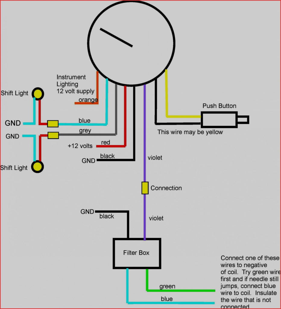
The negative end of the chassis must be connected to connect to the coil’s lower-tension end. This is what is known as the ground for the ignition wiring. The high-tension side supplies positively direct to the spark plugs. The aluminum body of the coil needs to be linked to the chassis for suppression however it’s not electrically required. You will also see the connections of the negative and positive coil’s terminals on an diagram of the ignition wiring. There could be an ignition coil problem which can be identified by looking it up at the auto parts shop.
The black-and-white-striped wire from the harness goes to the negative terminal. The negative terminal is served by the trace in black that’s connected to the white wire. The contact breaker is attached to the black wire. If you’re not sure about the connection between both, you can use the clip of a paperclip to remove them from the plug housing. Be sure that you don’t bend the connectors.
Accessory terminals
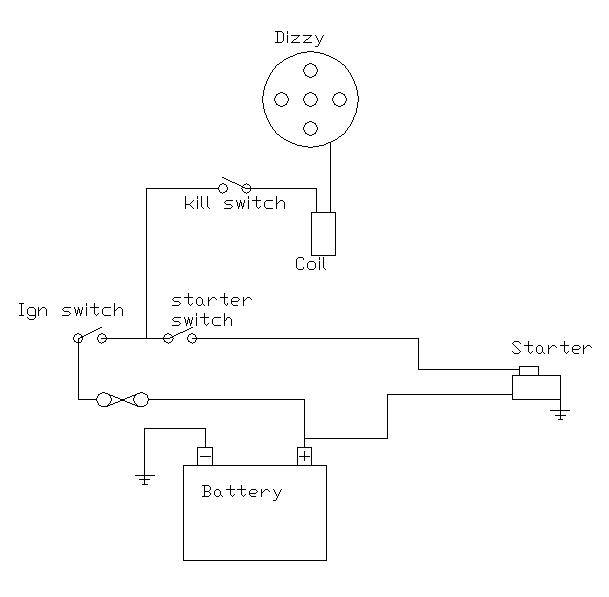
Diagrams of ignition wiring show the different wires that are used to power the car’s various components. There are usually four colors-coded terminus of each part. Red refers to accessories, yellow to the battery, and green is the starter solenoid. The “IGN” terminal lets you start your car, operate the wipers, and any other operation features. The diagram shows how you can connect the ACC and ST terminals to the rest of the components.
The terminal known as BAT is the location where the battery is. The electrical system won’t start without the battery. The switch also won’t be able to turn on without the battery. You may refer to the wiring diagram if you are uncertain about where the car’s batteries are. The accessory terminals of your car are connected with the battery and the ignition button. The BAT terminal is connected to the battery.
Some ignition switches are equipped with an additional position. This lets users access their outputs from another location without the ignition. Sometimes, customers wish to use an auxiliary output that is separate from the ignition. To make use of the auxiliary output, connect the connector in the same colors as ignition, and connect it to the ACC terminal on the switch. While this is a convenient feature, there’s one crucial distinction. Many ignition switches have an ACC position when the car is in ACC mode and a START mode when you are in IGN.
Gallery of Ice Ignition Wiring Diagram
Gallery of Ice Ignition Wiring Diagram


