Ignition Coil Pack Wiring Diagram – Let’s start by looking at the different types of terminals on an ignition switch. These terminals include the Ignition switch as well as the Coil as well as the Accessory. Once we know the purpose of each kind of terminal, we are able to identify the parts of the ignition wiring. Then, we will discuss the roles of the Ignition switch and the Coil. Then, we’ll talk about the function of the Ignition switch and Coil.
Terminals of ignition switch
Three switches are found on the ignition switch. Each of these switches feeds the battery’s voltage to various locations. The ON/OFF state of the switch that controls the ignition is managed by the third switch, which delivers the choke with power when it is pushed. Different manufacturers use their own color-coding systems for the different conductors, which is explained in a different article. OMC utilizes the same system. An additional connector is included in the ignition switch for attaching a to a tachometer.
While most ignition switch terminals can be duplicated, the numbers might not be in line with the diagram. Check the continuity of each wire to make sure they’re properly connected to the ignition switches. A multimeter is an excellent instrument to verify the continuity. Once you’ve verified that the wires are in good condition, you are able to connect the connector. If your vehicle has an original ignition switch supplied by the factory (or an electrical loom) the wiring loom might differ from the one in your car.
You must first understand the ways in which the ACC outputs and auxiliary outputs work in order to join them. The ACC terminals and IGN terminals are the primary connections to the ignition switch. The START and IGN connections are the primary connections for stereo and radio. The ignition switch is the one that turns the engine of your car on and off. Older cars are identified with the letters “ACC”, “ST”, (for individual magneto cables) at the ignition switch terminals.
Terminals for coil
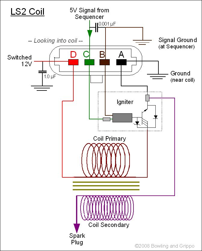
Understanding the terminology is the first step towards determining which type of ignition coil you own. A simple diagram of the wiring will reveal a variety of terminals and connections including two primary and two secondaries. It is essential to identify the kind of coil you own by examining the voltage at the primary terminal, S1. S1 must be checked for resistance to identify if the coil is type A, B and/or C.
The negative end of the chassis should be connected to connect the coil’s low-tension side. This is also the ground in the diagram of ignition wiring. The high-tension side delivers positively direct to the spark plugs. It is required to suppress the body of the coil’s metal be connected to its chassis, however, it is not necessary. It is also possible to see the connections between the positive and the negative coil’s terminals on an ignition wiring diagram. In some cases you’ll discover that an ignition coil that is malfunctioning can be diagnosed with scanning in an auto parts store.
The black-and-white-striped wire from the harness goes to the negative terminal. The white wire also is black with a trace, and it connects to the positive terminal. The black wire is connected to the contactbreaker. You can check the connections using a paperclip to take the wires out of the housing. It’s also essential to make sure the terminals aren’t bent.
Accessory terminals
The wiring diagrams of the ignition illustrate the different wires used to are used to power various components of the vehicle. In general there are four distinct color-coded terminals for each component. Red stands for accessories, yellow for the battery, and green for the starter solenoid. The “IGN terminal lets you start your car, operate the wipers or other operation features. The below diagram shows how to connect both the ACC terminal as well as the ST terminals to various components.
The terminal BAT is the connection to the battery. The electrical system can’t be started without the battery. Also, the switch won’t be able to turn on without the battery. If you’re not sure where your car’s battery is situated, you can look at your wiring diagram to figure out where it is. The accessory terminals in your car are connected to the battery as well as the ignition switch. The BAT connector is connected to your battery.
Some ignition switches have an “accessory” position that permits users to control their outputs , without needing to turn on the ignition. In some cases, users may want to use the auxiliary input separately from the ignition. To use the additional output, wire the connector using the same colors as the ignition and connect it to the ACC terminal on the switch. This feature is convenient however it does have one key distinction. Most ignition switches are configured to show an ACC status when the car’s at the ACC or START position.
Gallery of Ignition Coil Pack Wiring Diagram

Gallery of Ignition Coil Pack Wiring Diagram


