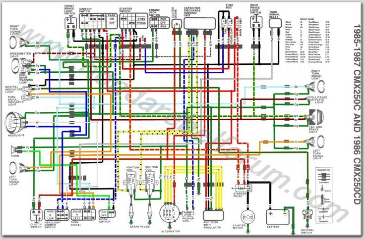
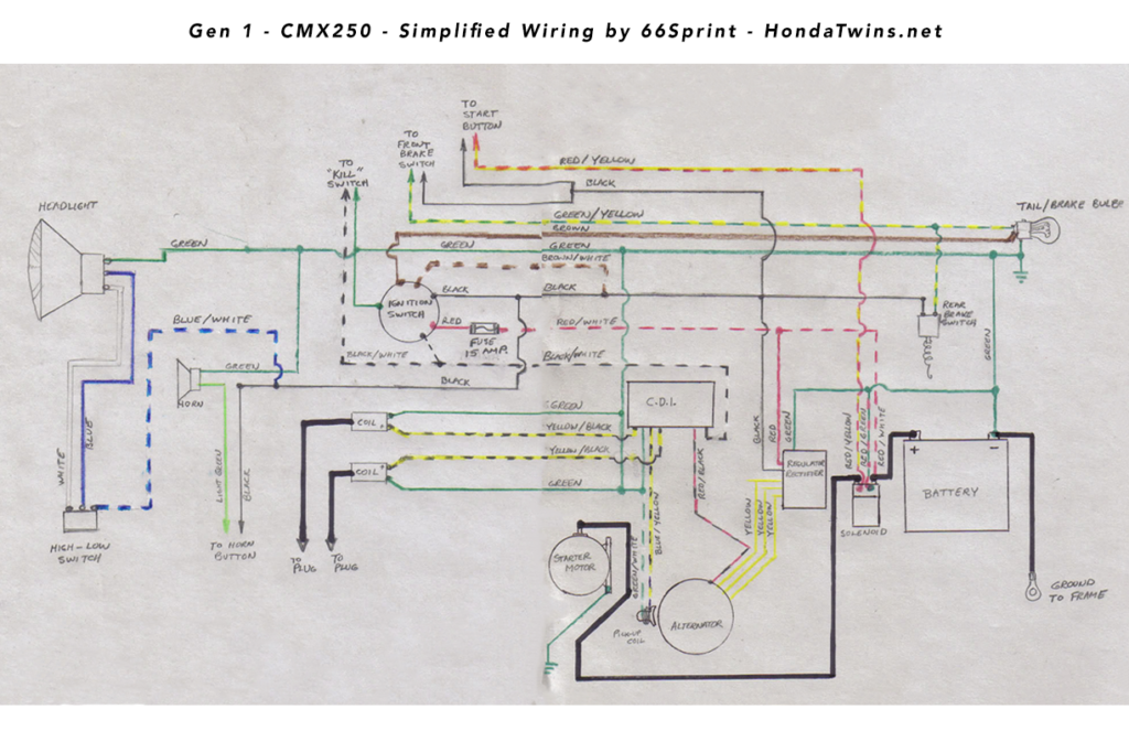
Ignition Honda Rebel 250 Wiring Diagram – The first step is to look at the different terminals on the ignition switch. These terminals serve for the Ignition button, Coil and Accessory. After we’ve established what these types of terminals are for then we can determine the various parts of the Ignition Honda Rebel 250 Wiring Diagram. In addition, we will discuss the function of the Ignition switch and Coil. Then, we’ll talk about the functions of the Ignition switch and Coil.
Terminals for ignition switch
The ignition switch is comprised of three different switches that direct the battery’s power to various locations. The first switch supplies the choke with power, while the second toggles the ON/OFF status of the ignition switch. Different manufacturers have different color-coding schemes for different conductors. We’ll discuss this in a different article. OMC follows this approach. The connector permits the connection of a speedometer to the ignition switch.
Even though the majority of ignition switch terminals don’t come in original form The numbering might not match that of the diagram. To make sure that your wires are plugged in to the ignition switch, it is recommended to check their continuity. This can be checked with a multimeter that is inexpensive. Once you are satisfied with the integrity of the wires, connect the new connector. The wiring loom used in an ignition system switch that is supplied by the manufacturer is distinct.
It is essential to know the ways in which the ACC outputs and auxiliary outputs function to join them. The ACC/IGN terminals act as the default connections for the ignition switch. The START/IGN terminals are connected to the radio or stereo. The ignition switch is responsible to turn the engine of your car on and off. The terminals of older vehicles’ ignition switches are labeled with “ACC” as well as ST (for specific magneto wires).
Terminals for coil
Understanding the terms utilized is the first step in finding out the right kind of ignition coil you need. A basic ignition wiring layout will show you a number of connections and terminals. Each coil comes with its own operating voltage. To determine which type of coil you have, the first step is to test the voltage at the S1 primary terminal. S1 should also be tested for resistance in order to identify if the coil is a Type B, B, or A coil.
The low-tension coil side must be connected at the chassis’ less. This is what’s called the ground in the wiring diagram for ignition. The high-tension side provides the spark plugs with positive. The aluminum body of the coil has to be linked to the chassis to prevent it from being smothered but isn’t required. The wiring diagram of the ignition will show you how to connect the terminals of the positive or negative coils. In some cases you’ll discover that the ignition coil is damaged and can be diagnosed with scanning at an auto parts store.
The black-and-white-striped wire from the harness goes to the negative terminal. The other white wire is black with a trace, and connects to the positive terminal. The black wire connects to the contact breaker. To check the connections between the two wires, employ a paperclip to remove them out of the housing. Be sure the terminals don’t bend.
Accessory terminals
The ignition wiring diagrams illustrate the different wires that are used to power the car’s various parts. There are typically four terminals with color codes that are connected to the respective component. Red is for accessories, yellow is for the battery, and green is for the solenoid for starters. The “IGN” terminal lets you start the car, control the wipers, and any other functions. The diagram demonstrates how to connect the ACC and ST terminals to the rest of the components.
The terminal BAT connects the battery to the charger. The electrical system can’t be started without the battery. The switch will not turn on if there is no battery present. To find your car’s battery examine the wiring diagram. Your car’s accessory terminals connect to the ignition switch as well as the battery. The BAT terminal is connected to the battery.
Certain ignition switches have an additional position in which users can modify their outputs and manage them without having to turn on the ignition. Sometimes, users want to make use of an additional output independent of the ignition. You can use the additional output by connecting the connector to an ACC terminal on the switch that has the same color. Although this is a great feature, there’s one thing to be aware of. Most ignition switches will be in an ACC position if the car is in the ACC however, they’ll be at the START position if the vehicle is IGN.
Gallery of Ignition Honda Rebel 250 Wiring Diagram
Gallery of Ignition Honda Rebel 250 Wiring Diagram


