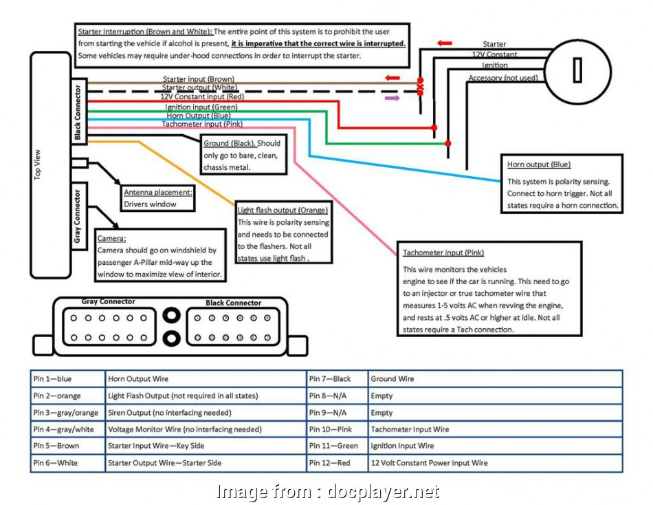
Ignition Interlock Device Intoxalock Wiring Diagram – Let’s first look at the different terminals that are used in the ignition switch. These are the terminals that connect the Ignition, Coil, or Accessory. After we’ve identified the purpose of these terminals, we can recognize the various parts of the ignition wiring. We will also discuss the roles of the Ignition switch and Coil. Following that, we will move on to the Accessory Terminals.
Ignition switch terminals
An ignition switch is comprised of three switches. They supply the voltage of the battery to different locations. The choke is powered by the first switch. The second switch is responsible for the ON/OFF switch of the ignition switch. Different manufacturers use different color-coding methods for different conductors. We will cover this in a separate article. OMC uses this method. The connector allows for the connection of a speedometer to the ignition switch.
While many ignition switch terminals could not be authentic, the numbering of each one might not be in line with the diagram. Check the continuity of all wires to ensure that they are properly connected to the ignition switches. This can be accomplished using a cheap multimeter. Once you are satisfied that all wires are in good order and you are able to connect the new connector. The wiring loom of a factory-supplied ignition system switch differs.
Before you can connect the ACC outputs to your car’s auxiliary outputs it is crucial to know the fundamentals of these connections. The ACC and IGN connectors are the standard connections for your ignition switch. Although the START, IGN, and ACC terminals are the primary connections for the radio or stereo, the START/IGN terminals are the primary ones. The ignition switch is the one that turns the car’s engine on and off. The ignition switch terminals on older cars are labeled with the initials “ACC” as well as “ST” (for the individual magneto wires).
Terminals for coil
The first step in determining the type of ignition coil is to understand the terminology employed. In a simple diagram of the wiring for ignition there are various connections and terminals, such as two primary and two secondary. Each coil is equipped with a distinct operating voltage. To determine which type of coil you have the first step is to test the voltage at S1, the primary terminal. S1 should also be checked for resistance to determine if it’s an A, Type B, or an A coil.
The low-tension side of the coil needs to be connected to the chassis the negative. This is also the ground on the ignition wiring diagram. The high-tension supply delivers positive directly to spark plugs. It is necessary for suppression purposes that the metallic body of the coil is connected to the chassis, but not essential. The ignition wiring diagram will also outline the connection of the positive coil terminals. In some cases, a scan at your local auto parts store can help you identify malfunctioning ignition coils.
The black-and-white-striped wire from the harness goes to the negative terminal. The positive terminal is connected to the white wire, which has a black trace. The black wire is connected to the contactbreaker. It is possible to check the connections with a pencil to remove the wires of the housing. Check that the terminals aren’t bent.
Accessory terminals
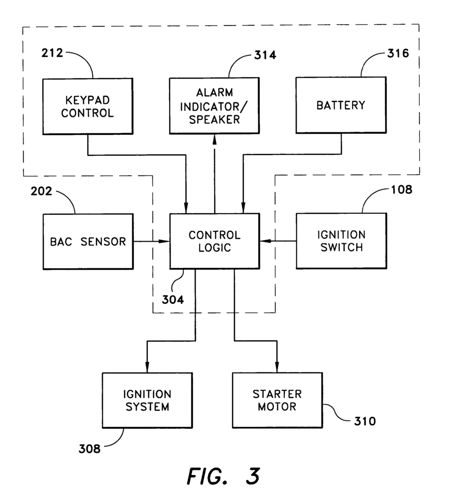
Diagrams of ignition wiring depict the wiring used to power various parts of the car. There are typically four colored terminals that correspond to the respective component. The accessories are colored red while the battery is yellow and the starter solenoid green. The “IGN” terminal is used to turn on the car and operate the wipers and other operating functions. The diagram below shows how to connect the ACC terminal and ST terminals to the other components.
The terminal BAT connects the battery to the charger. The electrical system will not start if the battery isn’t connected. Additionally, the switch doesn’t turn on. You may refer to the wiring diagram if you’re unsure where your car’s batteries are. The ignition switch and battery are connected through the accessory terminals. The BAT terminal is connected to the battery.
Certain ignition switches have an additional position in which users can alter their outputs and control them without the need to use the ignition. Sometimes, a customer wants to make use of an auxiliary output that is separate from the ignition. In order to use the auxiliary output, wire the connector in identical colors to the ignition and connect it to the ACC terminal on the switch. This is an excellent option, but there’s one important difference. A majority of ignition switches feature an ACC position when your vehicle is in ACC mode and a START position when you are in IGN.
Gallery of Ignition Interlock Device Intoxalock Wiring Diagram
Gallery of Ignition Interlock Device Intoxalock Wiring Diagram


