Ignition Interlock Device Wiring Diagram – The first step is to take a look at the different types of terminals used on the ignition switch. These are terminals that are used for Coil, Ignition Switch, and Accessory. Once we know the terminals that are utilized, we can begin to determine the various components of the Ignition Interlock Device Wiring Diagram. We’ll also discuss the roles of both the Ignition Switch and Coil. Then, we’ll turn our attention to Accessory terminals.
Terminals for ignition switches
There are three different switches on an ignition switch that transmit the battery’s current voltage to several different places. The first switch powers the choke. The second switch controls the ON/OFF function of the ignition switch. Different manufacturers use different colors-coding systems to match the conductors. OMC uses this method. The connector permits the attachment of a speedometer the ignition switch.
Although the majority of ignition switch terminals are not original, the numbers for each might not be consistent with the diagram. Check the continuity of all the wires to ensure that they are properly connected to the ignition switches. A multimeter is a good instrument to verify the continuity. After you’re happy with the continuity of your wires, you’ll be able install the new connector. If your vehicle is equipped with an ignition switch installed, the wiring diagram will differ.
Knowing how the ACC outputs connect to the other outputs in your car is essential. The ACC terminals as well as the IGN terminals are the primary connections to the ignition switch. The START and IGN connections are the main connections for radio and stereo. The ignition switch is responsible for turning the car’s engine on and off. Older vehicles have ignition switch terminals labeled “ACC” or “ST” (for individual magnetowires).
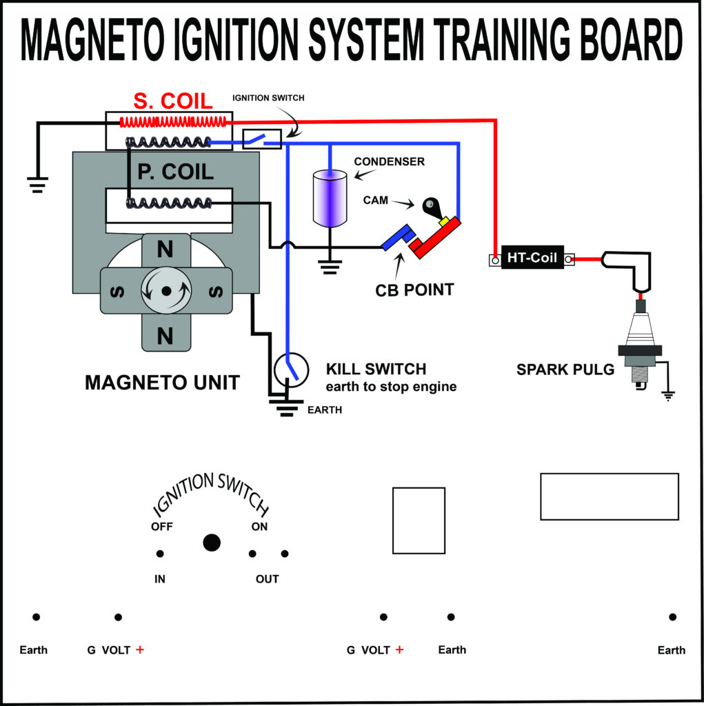
Terminals for coil
Understanding the terminology utilized is the first step in finding out the right type of ignition coil. An ignition wiring diagram will display a range of terminals and connections, including two primary and two secondaries. You must determine the type of coil you are using by testing the voltage at the primary terminal, S1. S1 must be checked for resistance to determine if the coil is Type A, B, and/or C.
The coil’s low-tension end must be connected with the chassis’ positive. This is the wiring diagram you will see in the wiring diagram. The high-tension supply delivers the spark plugs with positive electricity directly. It is essential to suppress the coil’s metallic body be connected to its chassis but not essential. A wiring diagram can show the connection between the positive and negative coils. In certain cases, a scan at the local auto parts store will help identify the malfunctioning ignition coils.
The black-and-white-striped wire from the harness goes to the negative terminal. The white wire is the other one. It has a black trace on it and connects to the positive terminal. The black wire connects to the contact breaker. It is possible to check the connections with a pencil to pull the wires out from the housing. Be sure that the terminals aren’t bent.
Accessory terminals
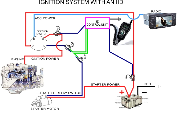
Diagrams of the ignition wiring illustrate the wires that power various parts of the car. There are usually four color-coded terminals that correspond to the component. Red is for accessories, yellow is for the battery, and green is for the starter solenoid. The “IGN” terminal allows you to start the car, control the wipers, and any other functions. The diagram shows how you can connect the ACC and ST terminals to the rest of the components.
The terminal referred to as BAT is where the battery is connected. Without the battery the electrical system can not get started. Furthermore the switch isn’t turned on. If you’re not sure of the location of your car’s battery located, you can examine your wiring diagram to figure out where it is. The ignition switch as well as the battery are connected through the accessory terminals. The BAT terminal is connected to the battery.
Some ignition switches have the “accessory” setting that allows users to control their outputs , without needing to utilize the ignition. Customers may want to utilize the auxiliary output independently of the ignition. The auxiliary output can be connected to connect the connector in the same color as your ignition and connecting it to the ACC terminal of the switch. This convenience feature is great, but there is one distinction. Most ignition switches will have an ACC position if the car is in ACC however they will be at the START position when the car is in IGN.
Gallery of Ignition Interlock Device Wiring Diagram

Gallery of Ignition Interlock Device Wiring Diagram


