Ignition Solenoid Wiring Diagram – Let’s first examine the different kinds and functions of terminals that are found in the ignition switches. These include the terminals that are for the Ignition switch, Coil, and Accessory. Once we have identified which terminals are used then we can determine the various components of the Ignition Solenoid Wiring Diagram. We will also cover the different functions of the Ignition Switch and the Coil. Following that, we’ll shift our attention to Accessory terminals.
Terminals for ignition switches
There are three switches on the ignition switch, and they feed the battery’s voltage to various locations. The first switch powers the choke. The second switch controls the ON/OFF function of the ignition switch. Different manufacturers use their own color-coding systems for different conductors which is explained in a different article. OMC follows the same system. A tachometer adapter is installed on the ignition switch to allow the installation of a tonometer.
Although the majority of ignition switch terminals do not have an initial number, they could have a different number. Before you plug into the ignition switch, make sure to check the continuity. You can check this using an inexpensive multimeter. When you are happy with the continuity of the wires, install the new connector. If your vehicle is equipped with an ignition switch installed, the wiring diagram will differ.
It is important to understand the ways in which the ACC outputs and auxiliary outputs function in order to join them. The ACC terminals and IGN terminals serve as the default connections to the ignition switch. The START and IGN connections are the primary connections for stereo and radio. The ignition switch’s function is to turn the car’s engines on and off. On older vehicles the ignition switch’s terminals are marked with the alphabets “ACC”, and “ST” (for distinct magnet wires).
Terminals for coil
To identify the kind of ignition coil you need to know the step is to learn the terminology. A basic ignition wiring diagram will reveal a variety of terminals and connections, comprising two primary and two secondaries. It is essential to identify the kind of coil you own by examining the voltage at the primary terminal, S1. S1 should also undergo resistance tests to determine if it’s a Type A or B coil.
The chassis’ negative needs to be connected to the low-tension side. This is the ground of the ignition wiring. The high-tension side delivers the positive power directly to the spark plugs. It is necessary to suppress the body of the coil’s metal be connected to the chassis, however it isn’t essential. It is also possible to see the connections between the positive and negative coil’s terminals on the ignition wiring diagram. Sometimes, a check at an auto parts store could identify a problem with the ignition wire.
The black-and-white-striped wire from the harness goes to the negative terminal. The other white wire has a black trace on it and connects to the positive terminal. The black wire connects to the contact breaker. If you’re unsure of the connections of both, you can use the clip of a paperclip to remove them from the plug housing. Make sure you check that the terminals have not been bent.
Accessory terminals
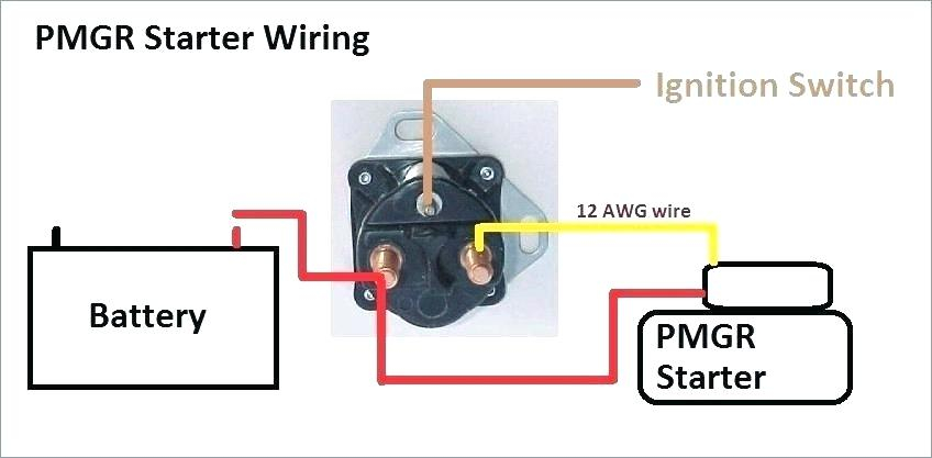
Diagrams of ignition wiring show the various wires utilized to power the vehicle’s various components. There are generally four colors of terminals connected to each part. The red color is for accessories, yellow is the battery, and green is the starter solenoid. The “IGN” terminal can be used to turn on the car, control the wipers, and other functions. The diagram shows how you can connect the ACC and ST terminals to the rest of the components.
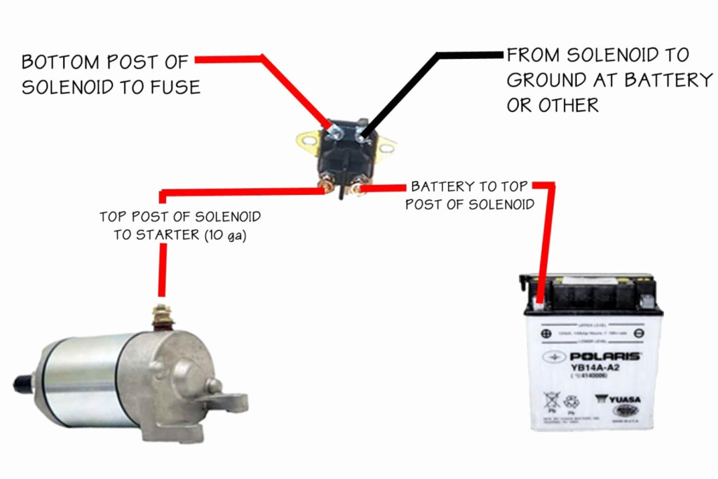
The terminal known as BAT is the place where the battery is. The electrical system can’t start without the battery. The switch won’t be able to turn off if the battery isn’t present. If you’re not sure the exact location where the battery in your car is situated, you can review your wiring diagram to figure out where it is. The ignition switch and battery are connected by the accessory terminals. The BAT terminal is connected with the battery.
Some ignition switches come with the option of an “accessory position” that lets users alter their outputs without the ignition. In some cases, users may want to use the auxiliary input separately from the ignition. In order to use the auxiliary output, wire the connector using the same colors as ignition, connecting it to the ACC terminal on the switch. While this is a convenient option, there’s an important difference. Some ignition switches are configured to be in an ACC location when the car has moved into the ACC position. They will also be in START mode after the vehicle has been moved into the IGN position.
Gallery of Ignition Solenoid Wiring Diagram
Gallery of Ignition Solenoid Wiring Diagram


