Ignition Wiring Diagram For Motorcycle – First, we will take a look at the different kinds of terminals on the ignition switch. They are the terminals used for Coil, Ignition Switch, and Accessory. Once we know the terminals that are utilized then we can recognize the various parts of the Ignition Wiring Diagram For Motorcycle. In addition, we will discuss the roles of both the Ignition Switch and the Coil. Then, we’ll turn our attention to the Accessory terminals.
The terminals are for ignition switches.
There are three switches on an ignition switch that transmit the battery’s current voltage to various places. The first switch is the one that supplies power to the choke, while the second toggles the on/off state of the switch. Each manufacturer has their unique color-coding system, which we will discuss in another article. OMC utilizes this system. An adapter is included on the ignition switch that allows for the addition of a tonometer.
Although the majority of ignition switch terminals may not be authentic, the numbering of each may not match the diagram. The first step is to check the continuity of all wires to make sure they’re properly connected to the ignition switches. This can be checked with a multimeter that is inexpensive. When you’re satisfied that the wires are running in good harmony then you can connect the new connector. The wiring loom used in an ignition system switch that is supplied by the manufacturer differs.
It is important to understand the ways in which the ACC outputs and the auxiliary outputs function to connect them. The ACC and IGN connectors are the standard connections of the ignition switch. While the START, IGN, and ACC terminals are primary connections for radios or stereo, the START/IGN connections are the primary ones. The ignition switch is responsible to turn the car’s engines on and off. On older vehicles the ignition switch’s terminals are identified with the alphabets “ACC”, and “ST” (for distinct magnetic wires).
Terminals for coil
The terminology used to determine the type and model of the ignition coil is the most important thing. A simple diagram of the wiring will show a variety of terminals and connections which include two primary terminals and two secondaries. Each coil operates at a specific voltage. The first step to determine the kind of coil you’re using is to examine the voltage of S1 or the primary terminal. S1 should be examined for resistance to determine if the coil belongs to Type A, B, or C.
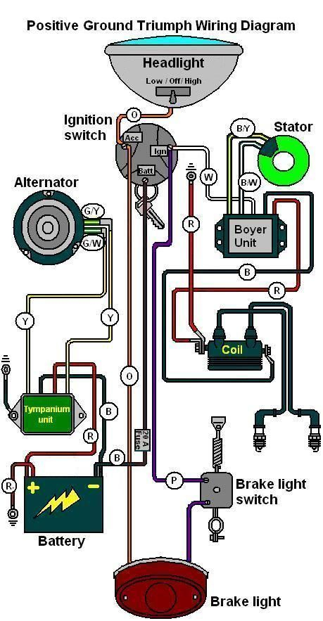
The low-tension coil side must be connected at the chassis’ less. This is exactly what you can see in the diagram of wiring. The high-tension component supplies positive direct to the spark plugs. To reduce the noise the coil’s body metal must be connected to the chassis. It’s not necessary for electrical use. The diagram of the ignition wiring will also reveal how to connect the negative and positive coil’s terminals. In certain instances it is recommended to conduct a scan at your local auto parts store will help identify malfunctioning ignition coils.
The black-and-white-striped wire from the harness goes to the negative terminal. The white wire is the other one. It has a black trace on it and connects to the positive terminal. The black wire connects to the contact breaker. It is possible to check the connections using a paperclip to remove the wires from the housing. Be sure the terminals aren’t bent.
Accessory terminals
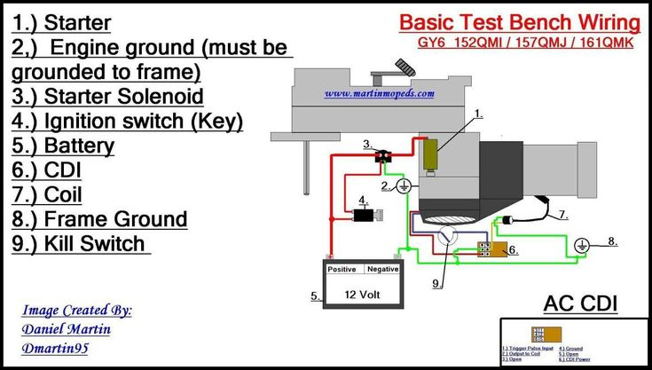
The ignition wiring diagrams show the different wires used to power the various components. There are typically four different color-coded terminus for each component. The accessories are colored red and the battery yellow and the starter solenoid is green. The “IGN terminal lets you start the car, control the wipers, or any other operation features. The diagram illustrates the connection of the ACCas well as ST terminals.
The battery is connected to the terminal named BAT. The electrical system can’t start without the battery. A dead battery can cause the switch to not turn on. If you’re not sure of the location of your car’s battery situated, look at your wiring diagram to see where it is. Your car’s accessory terminals connect to the ignition switch as well as the battery. The BAT connector is connected to the battery.
Certain ignition switches have an additional position in which users can alter their outputs as well as control them without the need to use the ignition. In some cases, users may want to use the auxiliary input separately from the ignition. You can use the additional input by connecting it to the ACC terminal. This option is useful, but it has one significant differentiator. Most ignition switches are set to operate in the ACC position when the car is in the ACC position, whereas they’re set to the START position when the car is in the IGN position.
Gallery of Ignition Wiring Diagram For Motorcycle
Gallery of Ignition Wiring Diagram For Motorcycle


