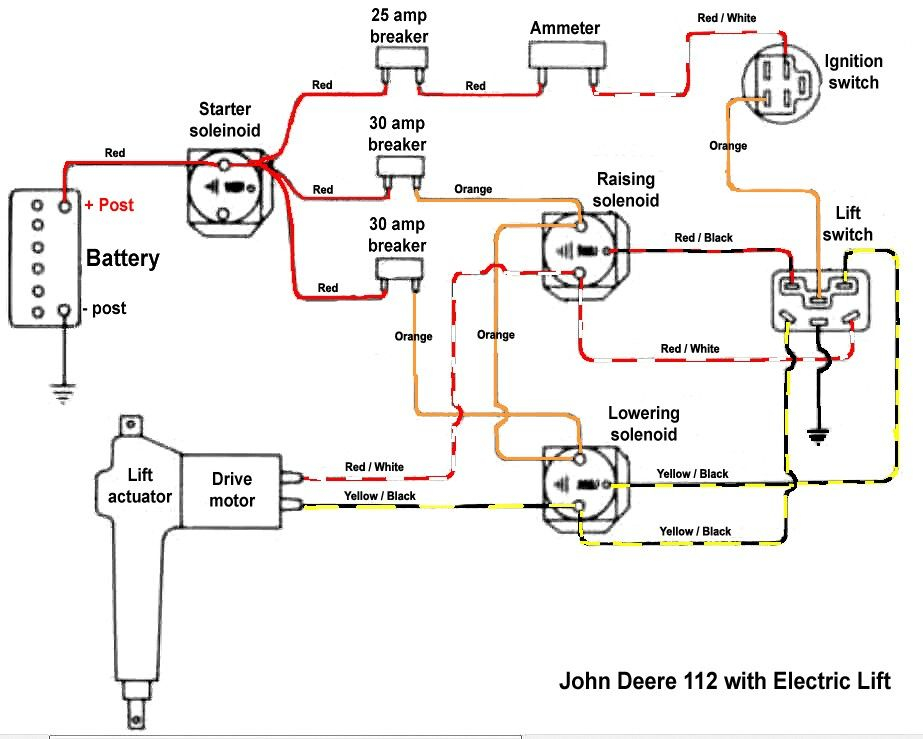
John Deere 112 Ignition Switch Wiring Diagram – First, we will take a look at the different kinds of terminals on the ignition switch. These terminals comprise the Ignition switch and Coil along with the Accessory. After we’ve identified the purpose of these terminals then we can be able to identify the various parts of the ignition wiring. We will also discuss the roles of the Ignition switch and Coil. Next, we’ll discuss the roles of the Ignition switch and Coil.
Terminals for ignition switch
An ignition switch has three switches. They feed the battery’s voltage to different places. The first is utilized to power the choke by pushing it, while another switch controls the ON/OFF position. Different manufacturers use different color-coding systems that correspond to the conductors. OMC uses this method. There is a connector in the ignition switch for attaching a to a tachometer.
While most ignition switch terminals can be duplicated, the number may not match the diagram. Verify the integrity of the wires first to make sure they’re connected correctly to the ignition switch. A multimeter is an excellent tool to check the continuity. When you’re satisfied with the continuity of your wires, you will be able to install the new connector. If your vehicle has an ignition switch installed the wiring diagram will differ.
In order to connect the ACC outputs to the auxiliary outputs of your car, you need to first understand how these two connections work. The ACC, IGN and START terminals are your default connections to the ignition switch. They also function as the primary connections to your radio and stereo. The ignition switch operates the engine’s on/off button. Older cars have the ignition switch terminals labeled “ACC” or “ST” (for individual magnetowires).
Terminals for coil
To identify the kind of ignition coil, the initial step is to understand the terminology. The diagram of the basic ignition wiring depicts various connections and terminals. There are two primary and secondary connections. You need to determine the kind of coil you own by examining the voltage on the primary terminal S1. It is also recommended to test S1 for resistance in order to identify if it’s a Type A, B, or C coil.
The low-tension side of the coil must be connected to the chassis’ negative. This is what is known as the ground for the ignition wiring. The high-tension side delivers positive direct to the spark plugs. The coil’s metal body needs to connect to the chassis to prevent it from being smothered, but it is not electrically required. It is also possible to see the connections of the positive and the negative coil’s terminals on the diagram of the ignition wiring. In some cases, a scan at your local auto parts shop will be able to diagnose defective ignition coils.
The black-and-white-striped wire from the harness goes to the negative terminal. The terminal that is negative is served by the trace in black that’s attached to the white wire. The black wire connects to the contact breaker. If you’re unsure of the connection between the two, try using the clip of a paperclip to remove them from the housing of the plug. It is also important to see that the terminals aren’t bent.
Accessory terminals
Diagrams of ignition wiring depict the wires used to supply power to different parts of the vehicle. There are generally four color-coded terminals to each component. Red is used for accessories, yellow is for the battery, while green is for the solenoid for starters. The “IGN” terminal is used to start the car, controlling the wipers, and for other functions. This diagram shows how to connect ACC and ST terminals with the rest of the components.
The battery is attached to the terminal whose name is BAT. The electrical system won’t start in the event that the battery isn’t connected. The switch won’t turn off if the battery isn’t there. The wiring diagram will tell you where to find the battery of your car. The accessory terminals on your car are connected to the battery and the ignition switch. The BAT connector connects to your battery.
Certain ignition switches come with the “accessory” position that allows users to control their outputs without needing to turn on the ignition. Sometimes, users want to make use of an additional output that is independent of the ignition. The auxiliary output can be utilized to connect the connector with the same colors as your ignition and attaching it to the ACC terminal of the switch. This is a useful feature, however there’s an important distinction. Most ignition switches are set to have an ACC position when the vehicle is in the ACC position, whereas they’re in the START position when the car is in the IGN position.
Gallery of John Deere 112 Ignition Switch Wiring Diagram
Gallery of John Deere 112 Ignition Switch Wiring Diagram


