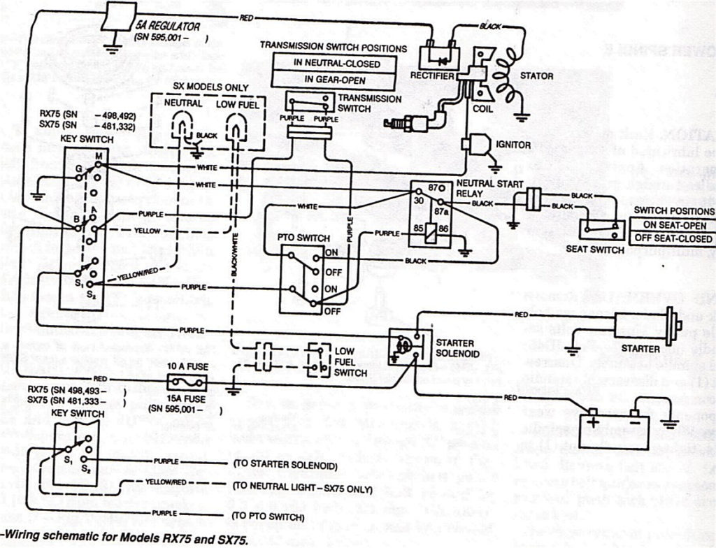
John Deere Rx75 Ignition Switch Wiring Diagram – First, we will examine the various types of terminals found in the ignition switch. These include the terminals that are for the Ignition switch, Coil, and Accessory. After we’ve identified the purpose of these terminals, we will be able to determine the various components of the ignition wiring. We will also discuss the roles of the Ignition switch and Coil. The next step is to focus on the accessory terminals.
Terminals for ignition switch
The ignition switch is comprised of three switches that supply the battery’s current to various destinations. The ON/OFF position of the ignition switch is controlled by the first switch, which supplies power to the choke whenever it’s pulled. Different manufacturers have different color-coding systems to identify different conductors. We’ll discuss this in a different article. OMC uses this method. The ignition switch also includes a connector for adding an Tachometer.
While most ignition switch terminals may not be original, the numbers for each may not match the diagram. Verify the integrity of the wires first to ensure that they are correctly plugged in the ignition switch. A multimeter is an excellent tool to check the continuity. Once you’re satisfied with the quality of the connection it’s time to connect the new connector. The wiring loom for an ignition switch that’s supplied by the factory will be different from the one you have in your vehicle.
It is important to understand how the ACC outputs and the auxiliary outputs function to join them. The ACC, IGN and START terminals are the default connection to the ignition switch. They are also the primary connections to the radio and stereo. The ignition switch is the engine’s off/on button. Older vehicles have ignition switch terminals marked “ACC” or “ST” (for individual magnetowires).
Terminals for coil
Understanding the terms used is the first step to determining what kind of ignition coil to choose. In a basic diagram of the wiring for ignition you’ll see several different connections and terminals, which include two primary and two secondary. Each coil comes with its own operating voltage. To determine the type of coil you own first, you need to determine the voltage at S1, the primary terminal. S1 must also be inspected for resistance to determine if the coil is a Type B, B, or A coil.
The negative end of the chassis should be connected to the coil’s low-tension end. This is also the ground on the wiring diagram for ignition. The high tension side supplies positive power directly to the spark plugs. The aluminum body of the coil needs to be connected to the chassis to prevent it from being smothered but isn’t required. The ignition wiring diagram will also indicate how to connect the positive coil’s terminals. In some cases, you’ll find that the ignition coil is damaged and is easily identified with a scan at an auto parts store.
The black-and-white-striped wire from the harness goes to the negative terminal. The positive terminal receives the other white wire, which has an black trace. The black wire is connected to the contactbreaker. It is possible to check the connections with a pencil to remove the wires from the housing. Make sure the terminals aren’t bent.
Accessory terminals
The wiring diagrams for the ignition show the various wires that power the various components of the vehicle. There are typically four different color-coded terminus for each component. For accessories, red is for starter solenoid, blue for battery and blue for accessory. The “IGN terminal lets you start the car, manage the wipers or other functions. The diagram illustrates the connection to the ACCas well as ST terminals.
The terminal BAT connects the battery to the charger. The battery is necessary to allow the electrical system to start. Furthermore the switch isn’t turned on. A wiring diagram can inform you where to find the battery in your car. The ignition switch as well as the battery are connected via accessory terminals. The BAT terminal is connected to the battery.
Some ignition switches come with the option of an “accessory position” that allows users to alter their outputs without the ignition. Some customers want the auxiliary output to be operated independently of the ignition. You can use the secondary input by connecting it to the ACC terminal. Although this is a useful option, there’s an significant difference. Most ignition switches are set to operate in the ACC position when the car is in the ACC position, whereas they’re in the START position when the vehicle is in the IGN position.
Gallery of John Deere Rx75 Ignition Switch Wiring Diagram
Gallery of John Deere Rx75 Ignition Switch Wiring Diagram


